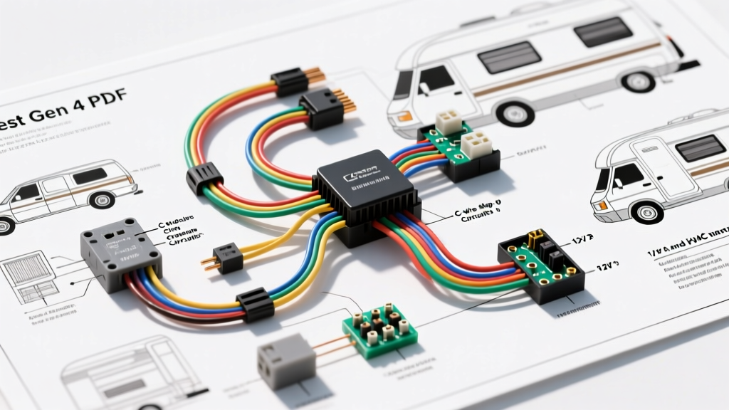
The Problem with the Nest Gen 4 Wiring Diagram PDF in Vehicles
When overlanders, skoolie builders, and custom car PC integrators search for and download the standard nest gen 4 wiring diagram pdf from residential HVAC resources, they immediately encounter a critical electrical roadblock. The Google Nest Learning Thermostat (4th Generation) is engineered for residential forced-air systems operating on 24V AC power. In contrast, automotive, marine, and RV environments operate on 12V or 24V DC systems. Attempting to wire a Nest Gen 4 directly to a 12V vehicle battery or a standard automotive relay harness will instantly destroy the thermostat's internal logic board and potentially short your vehicle's Body Control Module (BCM).
However, integrating a smart thermostat into a camper van or expedition vehicle to control a 12V diesel heater (like an Autoterm/Planar) or a 120V RV air conditioner via a contactor is entirely possible. It requires abandoning the residential wiring schematic and designing a custom DC-to-AC isolated power supply and relay harness. This guide provides the complete automotive-grade walkthrough for adapting smart home climate control to a mobile 12V DC architecture.
12V DC to 24V AC Isolated Power Supply Configuration
The Nest Gen 4 requires a continuous 24V AC feed across the R (Power) and C (Common) terminals to power its Wi-Fi radios, OLED display, and internal switching triacs. In a vehicle, you cannot simply use a DC-DC step-up converter, as the Nest requires alternating current to properly detect the state of its internal relays and avoid triac latch-up.
To solve this, you must install a 12V DC to 24V AC 40VA Isolated Transformer Module. These solid-state inverter modules are commonly used in off-grid solar HVAC controls. The isolation is critical: if the 24V AC circuit shares a common ground with the 12V DC vehicle chassis, you will create a ground loop that can introduce alternator whine into your vehicle's audio system or send parasitic AC voltage back into your 12V DC fuse bus, damaging sensitive automotive ECUs.
Wire Color Codes & AWG Specs for 12V RV Integration
When building the harness from your vehicle's 12V auxiliary fuse block to the thermostat baseplate, adhere to SAE J1128 standards for low-tension primary cable to ensure the wire insulation can withstand under-hood or interior cabin temperature fluctuations without becoming brittle.
| Circuit Function | Wire Color (SAE/RV) | AWG Size | Connector Type | Notes |
|---|---|---|---|---|
| 12V Constant (To Inverter) | Red | 12 AWG | Deutsch DT 2-Pin | Fused at 15A (ATC Blade) |
| 12V Ground (To Inverter) | Black | 12 AWG | Ring Terminal (1/4") | Direct to chassis, star washer |
| 24V AC Hot (Nest R) | Red | 18 AWG | Molex Micro-Fit 3.0 | From isolated transformer |
| 24V AC Common (Nest C) | Black | 18 AWG | Molex Micro-Fit 3.0 | Isolated AC ground only |
| Heat Trigger (Nest W) | White | 18 AWG | Molex Micro-Fit 3.0 | Switches 12V Bosch relay |
| Cool Trigger (Nest Y) | Yellow | 18 AWG | Molex Micro-Fit 3.0 | Switches AC compressor contactor |
Bosch 5-Pin Relay Harness for High-Current Vehicle HVAC
The internal switches on the Nest Gen 4 baseplate are designed to handle a maximum of 1.5 Amps at 24V AC. A standard 12V automotive diesel heater draws between 8A and 10A during the glow plug ignition phase, and a 12V RV AC compressor clutch can draw up to 15A. Routing this current through the Nest will melt the baseplate pins and destroy the unit. You must use the Nest to trigger the coil of an automotive relay.
For high-current inductive loads like compressor clutches or heater elements, we recommend using a Bosch-style 5-pin 12V 40A relay equipped with an internal flyback diode to suppress voltage spikes when the magnetic field collapses.
Pinout Configuration for Heat (Diesel Heater) Integration
- Terminal 86 (Coil +): Connect to the 24V AC Hot (R) wire via a rectifier diode, or use a dedicated 12V trigger wire if utilizing a smart relay board.
- Terminal 85 (Coil -): Connect to the Nest Gen 4 W (White) terminal. When the Nest calls for heat, it completes the circuit, energizing the coil.
- Terminal 30 (Common): Connect to a 12V DC battery positive via a 30A Maxi fuse.
- Terminal 87 (Normally Open): Connect to the positive trigger wire of the diesel heater control board or RV AC contactor coil.
- Terminal 87a (Normally Closed): Not used in this application; insulate and cap.
Expert Note: Because the Nest outputs AC voltage on the W terminal, and standard Bosch relays require DC to energize the coil efficiently without buzzing, you must install a full-wave bridge rectifier and a small smoothing capacitor (e.g., 470µF 35V) between the Nest W terminal and the relay coil. Alternatively, use a solid-state relay (SSR) with a zero-cross detector rated for 3-32V DC / 24-28V AC input.
Galvanic Isolation and Ground Loops
A frequent failure mode in custom vehicle HVAC wiring is the accidental bonding of the 24V AC Common (C-wire) to the 12V DC vehicle chassis ground. If your 12V-to-24V AC power supply is not galvanically isolated, the AC current will seek the path of least resistance through the vehicle's frame. This can result in stray voltage corrupting the CAN bus network, leading to phantom Check Engine Lights (CEL) or erratic instrument cluster behavior.
Always verify isolation using a digital multimeter (DMM). With the 12V DC power on and the 24V AC transformer active, set your DMM to AC Volts. Place one probe on the Nest C-wire terminal and the other on a bare metal chassis ground. The reading should be floating or near 0V. If you read 24V AC, your power supply lacks isolation and must be replaced immediately before connecting the thermostat baseplate.
Troubleshooting Voltage Drop and Parasitic Draw
In long wheelbase vehicles like the Mercedes Sprinter or Ford Transit, running 18 AWG thermostat wire from the rear electrical bay to the front cabin can result in significant voltage drop. While the Nest Gen 4 is tolerant of minor voltage fluctuations, dropping below 16V AC will cause the unit to reboot continuously or fail to engage the internal triacs.
Calculating Voltage Drop
Use the standard automotive voltage drop formula: VD = (2 x L x I x R) / 1000, where L is the one-way wire length in feet, I is the current in amps, and R is the resistance per 1000 feet of the wire gauge. For 18 AWG copper wire, R is approximately 6.385 ohms. If your wire run is 25 feet and the Nest draws 0.2A (200mA) in standby, the drop is negligible. However, during Wi-Fi transmission bursts, current can spike to 0.5A. Always route 18 AWG wire in a shielded twisted pair (STP) configuration to prevent electromagnetic interference (EMI) from the vehicle's alternator or high-voltage ignition coils.
Managing Parasitic Draw on the Starter Battery
The Nest Gen 4 draws approximately 1.5W to 2.5W in standby to maintain network connectivity and display wake-on-approach sensors. Over a two-week period of vehicle inactivity, this equates to roughly 4-5 Amp-hours of draw. Never wire the thermostat's 12V DC power supply to the vehicle's starter battery. Always connect it to the auxiliary/house battery bank via a dedicated DC distribution bus with a low-voltage disconnect (LVD) relay set to cut power at 11.8V to preserve cranking amps.