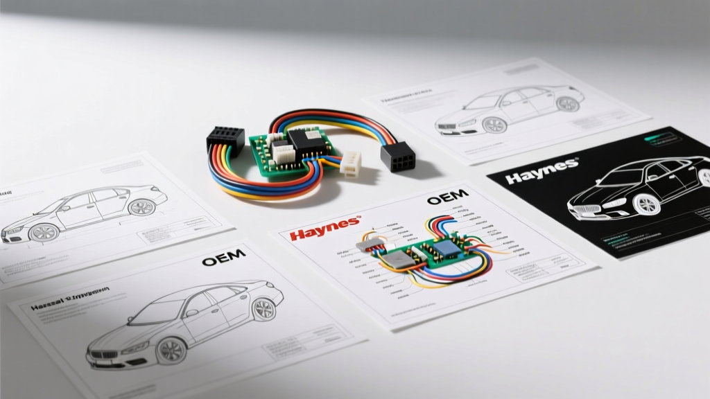
The Critical Role of Accurate Pickup Wiring Diagrams
Modern pickup trucks are no longer simple mechanical workhorses; they are rolling networks of high-current loads, multiplexed CAN bus systems, and sensitive powertrain control modules (PCMs). Whether you are installing a heavy-duty snow plow, troubleshooting a parasitic draw, or integrating an aftermarket trailer brake controller, relying on generic or incomplete schematics can lead to catastrophic electrical failures. Selecting the right pickup wiring diagrams is not just about finding a visual map of wires; it is about securing accurate connector end-views, precise wire color codes, AWG specifications, and splice pack locations. This guide compares the three primary sources of truck wiring schematics—OEM Factory Service Manuals, Aftermarket Print Guides, and Professional Digital Databases—to help you choose the right resource for your specific project.
Product Comparison: The Big Three Diagram Sources
1. OEM Factory Service Manuals (FSM)
OEM FSMs are the gold standard for automotive electrical diagnostics. Published directly by the manufacturer (e.g., Ford Motorcraft, GM Service Information, Ram TechAuthority), these manuals provide exhaustive, vehicle-specific wiring diagrams. They include exact connector cavity numbers, terminal release tool specifications, and detailed ground distribution charts (e.g., G104, G201). The primary drawback is cost and accessibility; OEM manuals are often sold as expensive multi-volume print sets or require costly short-term subscriptions to the manufacturer's proprietary portal.
2. Aftermarket Print & Digital Manuals (Haynes/Chilton)
For decades, Haynes Publishing and Chilton have been the go-to resources for DIY mechanics. These manuals condense years of a specific pickup model into a single, affordable book. While they excel at basic circuit routing, starter/alternator wiring, and standard lighting circuits, they often fall short on modern truck complexities. Aftermarket diagrams frequently omit CAN bus network topologies, detailed PCM pinouts, and specific splice pack locations, grouping complex multiplexed circuits into simplified 'black box' representations.
3. Professional Digital Databases (ALLDATA / Mitchell1)
Professional repair databases like ALLDATA Professional and Mitchell1 ProDemand are what dealership technicians use daily. These platforms digitize the OEM FSMs, adding interactive wiring diagrams where you can click on a connector to view the exact pinout and cavity shape. They also integrate Technical Service Bulletins (TSBs) directly into the diagnostic flowcharts. While they require a monthly subscription, they are indispensable for professional shops and serious restorers dealing with late-model truck electronics.
Feature Comparison Matrix: Diagram Source Capabilities
| Feature | OEM FSM | Haynes / Chilton | ALLDATA / Mitchell1 |
|---|---|---|---|
| Connector End-Views & Pinouts | Excellent | Poor to Fair | Excellent |
| CAN Bus Network Topology | Excellent | Usually Omitted | Excellent |
| Ground Distribution Maps | Excellent | Fair | Excellent |
| TSB Integration | Separate Portal | None | Integrated |
| Cost to Consumer | High ($150-$300+) | Low ($30-$45) | Medium (Subscription) |
Technical Deep Dive: Why Generic Diagrams Fail on Modern Trucks
To understand why investing in high-quality pickup wiring diagrams is essential, consider two common truck-specific electrical systems where inferior diagrams lead to immediate failure.
The PCM-Controlled Alternator Circuit
On older trucks, an alternator simply required a 12V ignition source and a heavy gauge B+ output wire. Modern pickups (such as the GM Silverado/Sierra or Ford F-Series) utilize PCM-controlled smart alternators. These alternators use a 2-pin Metri-Pack 280 connector featuring an 'L' (Lamp/Ignition) terminal and an 'F' (Field/PWM) terminal. The PCM sends a Pulse Width Modulated (PWM) signal on the F-circuit (typically a 16 AWG or 18 AWG wire) to dictate alternator output based on battery temperature and electrical load. If an aftermarket diagram omits this PWM circuit and a DIYer attempts to wire the alternator directly to a switched 12V source, the PCM will lose voltage regulation control, resulting in a P0620 (Generator Control Circuit) code and potential battery overcharging.
SAE J286 7-Way Trailer Tow Circuits
Trucks are designed to tow, making the 7-way RV blade connector a critical circuit. Governed by the SAE International J286 standard, this circuit requires specific wire gauges to handle high current loads without excessive voltage drop. Generic diagrams often fail to specify the AWG requirements, leading to melted connectors when electric trailer brakes are applied.
| Pin | Function | Standard Wire Color | Minimum AWG | Notes / Failure Modes |
|---|---|---|---|---|
| 1 | Ground (White) | White | 10 AWG | Must handle return current for all lighting and aux circuits. |
| 2 | Tail / Marker | Brown | 16 AWG | Frequently victim of voltage drop if undersized. |
| 3 | Left Turn / Stop | Yellow | 16 AWG | Shared with brake circuit on standard setups. |
| 4 | 12V Aux / Charge | Black | 10 AWG | Requires 30A-40A relay; undersizing causes fire risk. |
| 5 | Right Turn / Stop | Green | 16 AWG | Shared with brake circuit on standard setups. |
| 6 | Electric Brakes | Blue | 12 AWG | High current draw; 12 AWG mandatory for safe braking. |
| 7 | Reverse / Aux | Purple | 16 AWG | Often used for reverse lockout solenoids on surge brakes. |
Selection Decision Tree: Which Source Fits Your Project?
Choosing the right pickup wiring diagrams depends entirely on the scope of your project and your technical expertise.
- The Weekend Warrior (Basic Maintenance): If you are replacing a headlight switch, installing a basic stereo, or swapping a tail light, a Haynes or Chilton manual is sufficient. The circuits are straightforward, and the simplified diagrams save time.
- The Heavy-Duty Upgrader (Towing & Plows): If you are wiring a 7-way tow harness, installing a snow plow relay kit, or adding high-draw off-road lighting, you need OEM FSMs or ALLDATA. You must know the exact capacity of the factory auxiliary fuse block and the location of the under-hood splice packs to avoid overloading the main harness.
- The Professional Diagnostician (CAN Bus & PCM): If you are diagnosing U-codes (network communication faults), tracing parasitic draws through the Body Control Module (BCM), or performing an engine swap, Professional Digital Databases (ALLDATA/Mitchell1) are mandatory. You need interactive diagrams to identify the 120-ohm CAN bus termination resistors and map the High-Speed (HS-CAN) and Low-Speed (MS-CAN) network gateways.
Common Truck Wiring Pitfalls to Avoid
Even with the best diagrams, truck wiring presents unique physical challenges. Always verify the physical wire color against the diagram, as mid-year production changes and previous owner modifications are common in the truck world. Furthermore, never ignore the ground distribution charts provided in OEM diagrams. A poor ground connection at a chassis point (often obscured by undercoating or rust) will mimic a failed module or a shorted wire. Finally, when working with modern truck CAN bus networks, remember that the twisted pair wires must remain twisted up to within 4 inches of the connector to prevent electromagnetic interference (EMI) from the heavy-current alternator and injector circuits.
Final Verdict on Pickup Wiring Diagram Selection
While aftermarket print manuals hold a nostalgic and practical place in the DIY garage, the electrical complexity of modern pickups demands more rigorous documentation. For any project involving the PCM, trailer towing networks, or CAN bus diagnostics, investing in OEM factory manuals or a subscription to a professional digital database will save you hours of frustrating multimeter probing and prevent costly module replacements. Always match your diagram source to the technical depth required by your specific truck project.