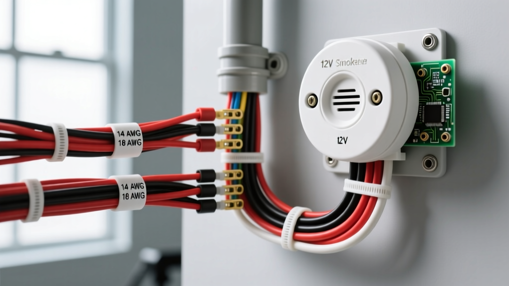
Introduction to 12V DC Fire Safety in Motorhomes
When outfitting a Class A, B, or C motorhome with modern safety equipment, understanding the specific electrical requirements of the RV environment is critical. Unlike residential homes that rely on 120V AC hardwired networks or standalone 9V battery units, recreational vehicles require specialized 12V DC hardwired systems. Standard residential smoke alarms are not designed to withstand the severe vibration, extreme temperature fluctuations, and 12V DC voltage spikes inherent to automotive and RV electrical systems. Furthermore, relying on battery-operated units in an RV is a safety hazard; batteries degrade rapidly in unclimatized storage, and vibration can dislodge internal contacts.
To achieve compliance with the NFPA 1192 Standard on Recreational Vehicles, motorhomes must utilize hardwired, 12V DC interconnected smoke detectors powered directly by the house battery bank. This practical how-to installation guide will walk you through reading and executing a 12V RV wiring diagram of smoke detector circuits, ensuring your rig is protected by a reliable, code-compliant fire detection network.
Decoding the Wiring Diagram of Smoke Detector Systems (12V DC)
A standard 12V DC RV smoke detector wiring schematic typically involves either a 2-wire (standalone) or 3-wire (interconnected) configuration. In a 3-wire setup, the third wire acts as a signal bus. If the detector in the bedroom senses smoke, it sends a 12V pulse down the interconnect wire to the detector in the main living area, triggering all alarms simultaneously. This is crucial in motorhomes where closed doors and ambient road noise can mask a single localized alarm.
The power source must originate from the 12V DC house battery distribution panel (often a Bussmann fuse block), not the chassis battery. This ensures the fire safety system remains active when the vehicle is parked and the ignition is off, while also preventing parasitic drain from disabling your engine starting battery.
Component Breakdown & Wire Specifications
Automotive environments demand high-temperature, vibration-resistant wiring. According to SAE J1128 standards, GXL (Cross-linked polyethylene) or TXL wire is mandatory for concealed RV ceiling runs due to its thin insulation and high heat resistance. Standard PVC THHN wire is prohibited in automotive/RV applications due to its susceptibility to melting and chafing.
| Wire Function | Standard RV Color Code | Wire Gauge (AWG) | Wire Type | Termination / Protection |
|---|---|---|---|---|
| 12V+ Constant Power | Red | 16 AWG | GXL Stranded | 5A ATC Blade Fuse (at source) |
| DC Ground | White | 16 AWG | GXL Stranded | Ring Terminal to Negative Bus Bar |
| Interconnect Signal | Yellow | 18 AWG | GXL Stranded | Heat Shrink Butt Splice |
Step-by-Step Hardwired Installation Guide
Before beginning any electrical work on your motorhome, disconnect the negative terminal on the house battery bank to prevent accidental short circuits. Gather your tools: wire strippers, a crimping tool, adhesive-lined marine-grade heat shrink tubing, and a digital multimeter.
Step 1: Route Planning and NFPA 1192 Compliance
The Recreational Vehicle Industry Association (RVIA) and NFPA dictate specific placement rules to avoid "dead air" spaces. Smoke rises and spreads laterally along the ceiling. Mount the detectors on the ceiling, at least 4 inches away from any sidewall corner. If mounting on a wall, the top of the detector must be between 4 and 12 inches from the ceiling. Never install a detector within 3 feet of an HVAC supply register, a bathroom door, or a kitchen cooking appliance, as dust and steam will cause nuisance tripping.
Step 2: Power Routing and Fuse Integration
Run the 16 AWG Red (power) and White (ground) wires from your Bussmann fuse block to the first detector location. Use existing wire chases or flexible nylon loom to protect the wires from sharp metal edges inside the RV ceiling cavity. At the fuse block, install a 5A ATC blade fuse for the smoke detector circuit. This low amperage is sufficient for the microcontroller and piezoelectric siren while providing rapid blow-protection against dead shorts.
Step 3: Termination and Heat Shrinking
Never use wire nuts in an RV. The constant vibration from driving will cause wire nuts to back off, leading to arcing or open circuits. Instead, strip 1/4 inch of insulation from the 16 AWG wires and use adhesive-lined heat shrink butt connectors to join the detector pigtails to your main harness. Apply heat until the adhesive oozes from the edges, creating a waterproof and vibration-proof seal. For the white ground wire, terminate it with a #10 ring terminal and secure it to a dedicated DC negative bus bar. Do not ground the detector to a random sheet metal screw; RV walls often contain non-conductive adhesives and composite materials that will prevent a proper chassis ground.
Interconnecting Multiple Detectors (Daisy Chain)
If your motorhome requires multiple detectors (e.g., one in the master bedroom, one in the bunk area, and one in the main salon), you must utilize the 3-wire interconnect feature. Run an 18 AWG Yellow wire from the "Signal" or "Interconnect" terminal of the first detector to the corresponding terminal on the second detector. When Detector A senses smoke, its internal relay closes, sending 12V down the Yellow wire. This voltage spike signals Detector B's microcontroller to sound its siren immediately. Ensure the Yellow wire is routed in the same loom as the Red and White wires to prevent electromagnetic interference (EMI) from external sources.
Voltage Drop Calculations for Long Wire Runs
Large Class A motorhomes can require wire runs exceeding 50 feet from the battery compartment to the rear bedroom ceiling. While a smoke detector's standby current is minimal (typically 50mA to 100mA), the inrush current when the 85-decibel piezo siren activates can spike to 1.5 Amps. If the wire gauge is too small, the voltage at the detector will drop below the 9V minimum operating threshold, causing the microcontroller to reset or the siren to sound weak and distorted.
Using the standard voltage drop formula: VD = 2 x L x I x R / 1000 (where L is length in feet, I is current, and R is wire resistance per 1000 ft). For a 50-foot run of 18 AWG wire (4.02 ohms/1000ft) pulling 1.5A, the voltage drop is roughly 0.6V. While this seems acceptable, accounting for connection resistance and aging battery states (which may sit at 11.8V instead of 12.6V) makes 16 AWG (2.52 ohms/1000ft) the mandatory choice for runs over 25 feet to guarantee reliable siren activation.
Real-World Troubleshooting & Diagnostics
Even with a flawless installation, 12V RV electrical systems can introduce anomalies. Use this diagnostic tree to resolve common issues:
- Symptom: Detector chirps intermittently at night.
Cause: Voltage drop caused by the 12V compressor fridge or inverter cycling on, pulling the house bank voltage down to 11.2V.
Fix: Verify wire gauge is 16 AWG or thicker. Check the main house battery bus connections for corrosion causing systemic voltage sag. - Symptom: False alarms when parked near high-tension power lines or running the microwave.
Cause: Electromagnetic Interference (EMI) inducing a phantom voltage on the sensor circuit.
Fix: Ensure the detector's wiring is not routed parallel to 120V AC inverter cables. If unavoidable, shield the 12V DC harness with braided copper shielding and ground the shield at the fuse block only. - Symptom: Interconnected alarms do not trigger together.
Cause: Open circuit on the Yellow interconnect wire, or mixed brands of detectors using incompatible signal protocols.
Fix: Test continuity on the Yellow wire with a multimeter. Ensure all detectors on the daisy-chain are the exact same make and model, as proprietary signaling varies between manufacturers like Kidde and First Alert.
By adhering to automotive wiring standards and respecting the unique electrical topology of a motorhome, your 12V smoke detection system will provide reliable, life-saving protection for every mile of your journey.