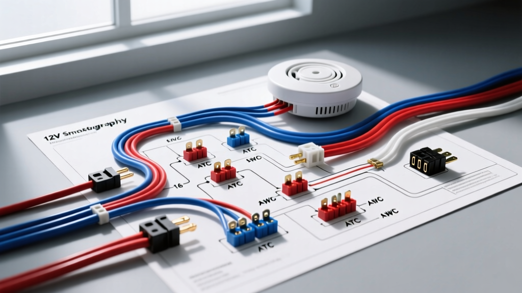
Why Hardwire 12V Smoke Detectors in RVs and Campers?
When outfitting a Class B camper van, expedition truck, or travel trailer, relying on standard 9V battery-powered residential alarms is a critical safety oversight. Vibrations from corrugated roads frequently dislodge battery contacts, and extreme temperature fluctuations in unclimatized vehicle cabins cause rapid battery depletion. For off-grid and overland vehicles, integrating a hardwired 12V DC system is the only reliable solution. This comprehensive guide provides a detailed cost and tool requirements analysis alongside a complete wiring diagram for smoke detectors designed specifically for 12V automotive and RV house-bank electrical systems.
By tapping directly into your auxiliary lithium or AGM house battery bank, you eliminate the risk of dead batteries and ensure continuous monitoring of smoke and carbon monoxide (CO). However, executing this requires adherence to strict automotive wiring standards, proper circuit protection, and specialized crimping tools to prevent voltage drop and parasitic drain.
Cost Analysis: Budgeting for a Hardwired 12V Safety Circuit
Upgrading from cheap residential alarms to a hardwired automotive-grade 12V system requires a modest upfront investment. Below is a detailed cost breakdown for a dual-zone RV setup (e.g., one near the sleeping area, one near the galley/kitchen).
| Component | Specification | Estimated Cost |
|---|---|---|
| 12V RV Smoke/CO Detector | Kidde or First Alert 12V DC Hardwired (UL Listed) | $55.00 - $75.00 |
| Primary Wire | 16 AWG TXL (Cross-Linked Polyethylene) Duplex | $1.80 / ft |
| Circuit Protection | ATC Inline Fuse Holder + 2A Blade Fuse | $8.50 |
| Terminals | Adhesive-Lined Heat Shrink Ring Terminals (16-14 AWG) | $14.00 / box |
| Busbars | Marine-grade Positive/Negative Busbars with covers | $35.00 |
| Master Kill Switch | Heavy Duty Battery Disconnect (for winter storage) | $45.00 |
Total Estimated Material Cost: $115.00 - $140.00 for a complete, NFPA-compliant dual-zone installation. While higher than buying a $15 battery-operated unit from a hardware store, the reliability and integration into your vehicle's battery management system (BMS) justify the expense.
Essential Tool Requirements for Automotive-Grade Terminations
The leading cause of electrical fires and false low-voltage alarms in RVs is poor termination. You cannot use standard pliers for automotive crimps. The following tools are mandatory for executing this wiring diagram for smoke detectors safely:
- Ratcheting Crimper (Insulated Terminals): Tools like the IWISS IWS-1400B or Knipex PreciForce ensure a gas-tight crimp on heat-shrink ring terminals. A gas-tight crimp prevents oxygen and moisture from entering the wire barrel, eliminating galvanic corrosion.
- Precision Wire Strippers: Capable of cleanly stripping 16 AWG to 22 AWG without nicking the copper stranding. Nicked strands reduce the wire's ampacity and create hot spots.
- Digital Multimeter (DMM): Essential for testing voltage drop across the circuit and measuring standby parasitic draw.
- Heat Gun with Reflector Nozzle: Required to evenly shrink adhesive-lined terminals. The internal adhesive melts and seals the wire insulation, providing complete moisture ingress protection (IP67 rating).
RV 12V Wiring Diagram For Smoke Detectors: Circuit Logic
The circuit logic for a 12V hardwired smoke detector prioritizes safety, voltage stability, and isolation from the vehicle's chassis ground. According to the NFPA 1192 Standard on Recreational Vehicles, alarms must be powered by the vehicle's primary or auxiliary electrical system and protected by an overcurrent device.
Wire Gauge and Insulation Standards
We specify 16 AWG TXL (Thin Cross-Linked) wire for this circuit. While the detector only draws roughly 50mA in standby and up to 150mA during an alarm event, 16 AWG is chosen for mechanical durability and to minimize voltage drop over long wire runs typical in Class C motorhomes or large travel trailers. TXL insulation is rated for 125°C, exceeding the SAE J1128 Low Tension Primary Cable Standard, making it highly resistant to abrasion and heat when routed near RV water heaters or engine bays.
Fusing and Circuit Protection
A 2A ATC (Automotive Blade) fuse is installed within 7 inches of the positive busbar source. This fast-acting fuse protects the 16 AWG wire from short circuits. While 16 AWG wire can technically handle 10A+ in free air, the 2A fuse is sized to protect the low-current internal logic board of the smoke detector in the event of an internal component failure.
The Chassis Ground Fallacy
Never use the vehicle's metal chassis for the negative return path of a hardwired RV smoke detector. Modern camper vans and expedition vehicles often feature composite bodies, aluminum framing with rubber isolators, or thick sound-deadening materials that create high-resistance ground paths. A poor ground will cause the detector's microprocessor to read a low-voltage state, triggering a continuous 'chirp' or failing to trigger the alarm horn during a fire. Always run a dedicated 16 AWG black wire back to the house battery's negative busbar.
Pinout and Connection Matrix
Most hardwired 12V RV smoke/CO detectors utilize a standardized 3-pin pigtail harness. Below is the exact pinout matrix for integrating the detector into your house bank.
| Wire Color | Function | Termination Point | Technical Notes |
|---|---|---|---|
| Red | 12V+ Constant Power | House Battery Positive Busbar (via 2A ATC Fuse) | Must be constant 12V. Do not route through an ignition-switched relay. |
| Black | DC Ground | House Battery Negative Busbar | Dedicated return path. Do not bond to chassis. |
| Yellow | Interconnect Signal | Daisy-chained to Secondary Detector Yellow Wire | Sends a 9V signal pulse to trigger secondary alarms in multi-zone RVs. |
For detailed best practices on busbar layout and circuit protection placement, refer to the Blue Sea Systems Circuit Protection Guide, which outlines the necessity of insulating covers on all positive distribution points to prevent accidental shorting against metal cabinetry.
Step-by-Step Installation & Voltage Drop Testing
Proper installation ensures the detector receives a minimum of 11.5V under all conditions. Follow these steps to execute the wiring diagram flawlessly:
- Disconnect Power: Turn off the main house battery disconnect switch and isolate the solar charge controller.
- Route the Wire: Run the 16 AWG duplex TXL wire from the house battery compartment to the ceiling-mounted detector location. Use grommets when passing through any sheet metal bulkheads to prevent insulation chafing.
- Crimp and Seal: Strip 3/8 inch of insulation. Insert into a #10 ring terminal (16-14 AWG). Use the ratcheting crimper. Apply heat evenly until the adhesive oozes from the terminal barrel.
- Terminate at Busbar: Secure the red wire to the positive busbar (with the 2A fuse installed) and the black wire to the negative busbar. Torque the busbar nuts to 25 in-lbs.
- Connect Detector: Use butt-splice heat-shrink connectors to join the harness pigtail to your routed TXL wire. Tuck the connections into the ceiling cavity, ensuring they do not pinch against the detector mounting plate.
- Voltage Drop Test: Reconnect power. Set your DMM to DC Volts. Place the red probe on the positive busbar and the black probe on the detector's red wire connection. The voltage drop should read less than 0.1V. If it reads higher, you have a high-resistance crimp that must be cut and redone.
Troubleshooting Parasitic Draw and False Alarms
Even hardwired systems can present issues if the vehicle's electrical environment is noisy or degraded. Use this diagnostic tree to resolve common faults:
Symptom: Detector Chirps Every 48 Hours
- Cause: Voltage at the detector pins is dropping below 10.5V, triggering the internal 'low battery' warning logic, even though the main house bank is fully charged at 13.4V.
- Fix: Perform a voltage drop test on both the positive and negative legs. Look for loose busbar connections, corroded ATC fuse blades, or undersized wire runs exceeding 40 feet. Clean fuse contacts with electrical contact cleaner.
Symptom: Excessive Parasitic Draw During Winter Storage
- Cause: A faulty detector logic board or an improperly wired interconnect (yellow) wire bleeding current to ground.
- Fix: Use your DMM in Amps mode (in series with the negative battery cable) to measure total standby draw. Isolate the 2A smoke detector fuse. If the parasitic draw drops significantly (normal standby is ~50mA per unit), replace the detector. If storing the vehicle for months, rely on the main house-bank kill switch rather than pulling individual fuses.
Symptom: False Alarms Triggered by Inverter Switching
- Cause: High-frequency electromagnetic interference (EMI) from a modified sine wave inverter or a poorly filtered high-wattage pure sine inverter is inducing voltage spikes in the detector's signal wire.
- Fix: Ensure the 12V detector wiring is routed at least 6 inches away from 120V AC inverter cables and high-amperage DC inverter supply cables. If necessary, wrap the detector harness in braided EMI shielding and ground the shield at the busbar end only.
Final Compliance and Safety Verification
Executing this wiring diagram for smoke detectors elevates your vehicle's safety profile from a makeshift DIY build to a professional, expedition-grade platform. By investing in 16 AWG TXL wire, ratcheting crimpers, and dedicated busbar returns, you ensure that your life-safety equipment remains operational regardless of the terrain, temperature, or state of charge of your auxiliary batteries. Always verify your final installation against local RV inspection standards and NFPA 1192 guidelines before embarking on remote overland journeys.