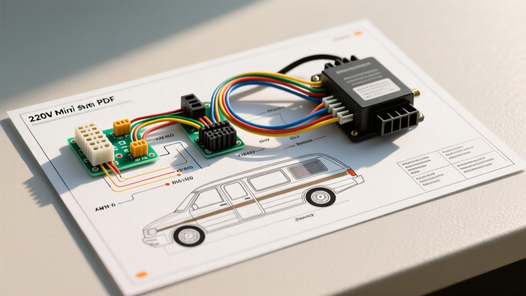
Integrating Residential Climate Tech into Expedition Vehicles
As the overland and luxury motorhome markets evolve, custom coachbuilders and DIY expedition vehicle converters are increasingly abandoning traditional 12V DC rooftop air conditioners in favor of high-efficiency, ductless inverter systems. When sourcing the 220v mini split wiring diagram pdf from manufacturers like Pioneer, Senville, or Mitsubishi, installers quickly realize that residential documentation does not account for the extreme vibration, electromagnetic interference (EMI), and dynamic power sourcing inherent to automotive and recreational vehicle (RV) environments. This complete wiring diagram walkthrough bridges the gap between residential HVAC schematics and the stringent requirements of mobile electrical systems, ensuring your Class A motorhome, Sprinter conversion, or heavy-duty expedition truck maintains precise climate control without tripping inverters or suffering from CAN bus interference.
Wiring a 220V (often nominally 208-230V) mini-split in a vehicle requires a deep understanding of both the HVAC manufacturer's terminal block pinouts and the RV's primary power distribution architecture. Whether you are tying into a 50-amp split-phase shore power pedestal or relying on a high-capacity 48V DC to 220V AC pure sine wave inverter bank, the physical routing, wire gauge selection, and shielding protocols must adhere to both NFPA and SAE standards for mobile applications.
Decoding the 220v Mini Split Wiring Diagram PDF for Mobile Use
The standard 220v mini split wiring diagram pdf provided in the installation manual typically illustrates a direct hardwired connection to a residential dual-pole breaker. In an expedition vehicle, this circuit originates either from the main AC distribution panel (shore/generator power) or the AC output bus of a high-frequency inverter/charger. The outdoor condenser unit serves as the primary power distribution point, stepping down voltage and routing communication signals to the indoor evaporator head.
Outdoor Condenser Terminal Block Pinout
The outdoor unit terminal block is where the primary high-voltage connections are made. For a standard 220V system, you will encounter four primary high-voltage terminals and a separate communication block.
- L1 (Line 1): Connects to the Black wire. In a 50-amp RV split-phase system, this is one of the 120V legs. In a single-phase 220V inverter output, this is the primary hot line.
- L2 (Line 2): Connects to the Red wire. On a residential 240V system, this is the opposing 120V leg. Note: Many modern DC inverter mini-splits are designed to operate on 208V-230V single-phase; verify if your specific unit requires a true 240V split-phase or if L1 and Neutral are sufficient for 220V European-style single-phase setups.
- N (Neutral): Connects to the White wire. Crucial for the control board logic and internal relays.
- Ground (Earth): Connects to the Green or Bare copper wire. In an automotive environment, this must be bonded to the vehicle's main AC ground bus, which is ultimately tied to the chassis ground and the shore power grounding conductor per NEC Article 551 (Recreational Vehicles).
Indoor Evaporator & Control Board Power
Unlike older window units, the indoor head unit of a mini-split rarely receives high-voltage AC power directly from the breaker panel. Instead, the 220v mini split wiring diagram pdf will show a 4-core or 5-core communication and power cable running from the outdoor condenser to the indoor evaporator. The outdoor unit's internal transformer and switching power supply step down the 220V AC to 12V-24V DC to power the indoor blower motor and logic board. This means the wiring harness passing through the vehicle's interior bulkhead is primarily low-voltage DC and digital communication, drastically reducing the fire hazard inside the living space.
Power Delivery: 50-Amp Shore Power vs. High-Capacity Inverters
Expedition vehicles utilize two primary methods to energize the 220V mini-split circuit. The wiring diagram must account for the transfer switch or automatic bypass logic of the inverter/charger.
When operating on 50-Amp Shore Power, the mini-split draws from the RV's main AC panel via a dedicated 15A or 20A dual-pole breaker. However, when boondocking, the system must rely on an inverter like the Victron Quattro 48/5000VA. Mini-split compressors, despite being 'soft-start' DC inverters themselves, draw a massive surge current (Locked Rotor Amps or LRA equivalent) for the first 500 milliseconds to charge the internal bus capacitors. If your inverter's surge rating is exceeded, it will fault, dropping AC power to the entire coach.
Wire Gauge & Breaker Sizing Specifications
| Mini-Split Capacity | Voltage | Max Running Amps | Breaker Size | AWG (Stranded Copper) | Wire Type (Mobile) |
|---|---|---|---|---|---|
| 9,000 BTU | 208-230V | 6.5A | 15A Dual-Pole | 12 AWG | MTW / THHN (Fine Strand) |
| 12,000 BTU | 208-230V | 9.0A | 15A Dual-Pole | 12 AWG | MTW / THHN (Fine Strand) |
| 18,000 BTU | 208-230V | 13.5A | 20A Dual-Pole | 10 AWG | MTW / THHN (Fine Strand) |
| 24,000 BTU | 208-230V | 18.0A | 25A Dual-Pole | 10 AWG | MTW / THHN (Fine Strand) |
Note: Solid core wire (ROMEX/NM-B) is strictly prohibited in mobile applications due to chassis harmonics causing metal fatigue and internal wire breakage. Always use marine-grade tinned copper or fine-strand MTW (Machine Tool Wire) secured with adhesive-lined heat shrink and vibration-resistant terminal lugs.
Communication Wire Routing & EMI Shielding
The most common point of failure when adapting a 220v mini split wiring diagram pdf for an automotive environment is the communication harness. The indoor and outdoor units communicate via a high-speed digital serial protocol over a 4-conductor 14 AWG cable. In a residential home, this cable is run alongside high-voltage lines without issue. In an expedition truck or motorhome, the cable must navigate a metal chassis saturated with electromagnetic noise from the alternator, solar charge controllers, and high-amperage DC-DC converters.
According to SAE J1113 Electromagnetic Compatibility standards, sensitive data lines in vehicles must be shielded. You must use a 4-core shielded twisted pair (STP) cable for the mini-split communication line. The critical error most installers make is grounding the shield drain wire at both the indoor and outdoor units. Because the vehicle's chassis and the AC ground bus can have varying electrical potentials, grounding both ends creates a ground loop, inducing noise that results in E1, E5, or E7 communication fault codes on the mini-split display.
Proper Shield Termination Protocol
- Run the shielded 14 AWG communication cable through a dedicated, flexible conduit separated from high-current DC battery cables by at least 18 inches.
- At the indoor evaporator unit, strip back the shield foil and trim the bare drain wire. Cap it with heat shrink so it does not make contact with the indoor unit's chassis or terminal block.
- At the outdoor condenser unit, terminate the bare drain wire to the designated Ground (Earth) terminal or a dedicated chassis grounding screw. This ensures high-frequency EMI is safely shunted to the vehicle's main ground bus at a single point.
Inverter Integration and Pure Sine Wave Requirements
If your expedition vehicle relies on an off-grid inverter system to run the 220V mini-split, the quality of the AC waveform is non-negotiable. The 220v mini split wiring diagram pdf assumes a clean utility grid sine wave. Modified Sine Wave (MSW) inverters will cause catastrophic failure to the mini-split's internal rectifier and PFC (Power Factor Correction) circuitry, often blowing the main board fuse and triggering an E7 (Compressor Drive Fault) or E9 (IPM Module Fault).
Only high-frequency, Pure Sine Wave (PSW) inverters with a low Total Harmonic Distortion (THD < 3%) should be used. Furthermore, when wiring the inverter's AC output panel, ensure the neutral-to-ground bonding relay inside the inverter/charger (such as those found in Victron Energy MultiPlus/Quattro systems) is functioning correctly. Mini-split control boards utilize the neutral-ground reference to detect leakage currents; an unbonded or floating neutral on the inverter output will cause the unit's internal GFCI or leakage protection to trip instantly upon startup.
Real-World Troubleshooting & Mobile Fault Codes
When a mini-split fails in a vehicle environment, standard HVAC diagnostics often fall short. Use this decision tree tailored for mobile installations:
Symptom: Unit trips the inverter upon startup (Inverter Overload Alarm)
- Cause: Capacitor charging inrush current exceeds the inverter's peak surge rating (often 10,000W+ for a split second).
- Fix: Install an aftermarket soft-start device (e.g., Micro-Air EasyStart) specifically wired into the compressor circuit, or upgrade the battery bank's DC cabling to 4/0 AWG to minimize voltage sag during the AC surge event.
Symptom: Intermittent E1 / E5 Communication Errors while driving
- Cause: Chassis vibration is causing micro-disconnects in the terminal block, or alternator whine is inducing EMI in the unshielded comm wire.
- Fix: Verify terminal block torque (typically 2.5 Nm to 3.0 Nm). Replace standard comm wire with MIL-spec shielded twisted pair and verify single-point shield grounding. Apply dielectric grease to the quick-disconnect spade terminals to prevent fretting corrosion.
Symptom: Evaporator blower runs, but compressor never engages (E7 Fault)
- Cause: Dirty power from a failing generator or MSW inverter damaging the outdoor IPM (Intelligent Power Module).
- Fix: Test AC source with an oscilloscope to verify pure sine wave and ensure voltage does not drop below 190V under load. If the IPM is damaged, the outdoor main PCB requires replacement.
By treating the 220v mini split wiring diagram pdf not as a rigid residential rulebook, but as a baseline electrical schematic that must be adapted to the harsh, high-vibration, and EMI-dense environment of a vehicle, converters can achieve reliable, whisper-quiet climate control capable of surviving the most demanding overland expeditions.