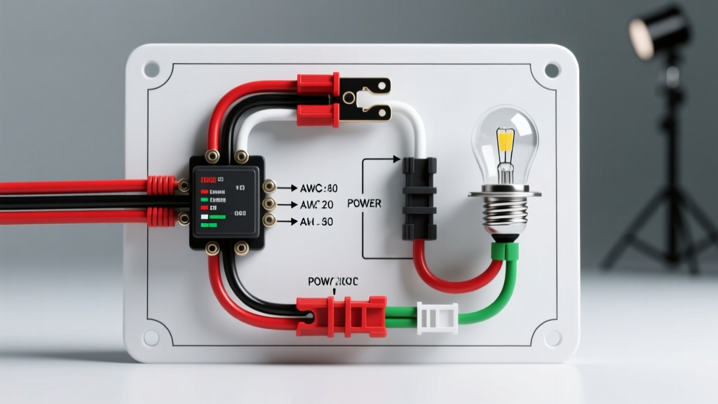
The Flaw in Factory Headlight Circuits
Most beginners assume that upgrading to higher-wattage halogen bulbs or installing modern LED assemblies simply requires plugging in a new bulb. However, without consulting a simple headlight wiring diagram and upgrading the harness, you risk melting your factory headlight switch or suffering severe voltage drop. Factory headlight circuits in many older vehicles (and some modern economy cars) route 12V power from the battery, through the firewall, into the dashboard switch, and all the way back out to the front headlights. This massive detour often utilizes undersized 16 AWG or 18 AWG wire, creating significant electrical resistance.
According to Daniel Stern Lighting Technical Articles, voltage drop is the enemy of automotive illumination. A standard H4 halogen bulb requires a solid 13.2V to 14.2V at the connector to produce its rated lumen output. If your factory wiring suffers a 2-volt drop due to resistance and aging copper, your headlights are operating at less than 70% of their potential brightness. The solution is a relay-based harness. By using a simple headlight wiring diagram centered around Bosch-style relays, you bypass the factory switch entirely for the heavy current load, using the switch only as a low-amperage trigger.
Deconstructing the Simple Headlight Wiring Diagram
A properly designed relay harness draws heavy current directly from the battery and delivers it straight to the headlight connectors via the shortest possible route. The factory headlight switch is relegated to triggering the relay's electromagnetic coil, which draws less than 0.2 amps. This eliminates voltage drop, protects your OEM multi-function stalk from melting (a notorious failure mode on GM GMT800 and older Honda platforms), and ensures maximum voltage at the bulb.
The Core Components
- Power Source: Direct connection to the battery positive terminal.
- Overcurrent Protection: An inline ATC/ATO blade fuse holder, positioned within 18 inches of the battery terminal.
- Switching Mechanism: Standard ISO/Bosch-style 4-pin or 5-pin automotive relay (typically rated for 30A or 40A).
- Trigger Source: Tapped into the OEM headlight positive wire or the parking light circuit.
- Output Connectors: Ceramic pigtails (H4/9003, H11, or 9005) to withstand high thermal loads.
Standard Bosch-Style Relay Pinout Guide
Understanding the relay is the most critical step in reading any simple headlight wiring diagram. The standard ISO mini-relay features four or five spade terminals, each assigned a specific DIN number. Below is the definitive pinout chart for a standard 4-pin SPST (Single Pole, Single Throw) relay used in headlight applications.
| DIN Pin | Function | Recommended Wire Color | Wire Gauge (AWG) | Connection Destination |
|---|---|---|---|---|
| 30 | Common (Power In) | Red | 12 AWG | Battery Positive (via Inline Fuse) |
| 87 | Normally Open (Power Out) | Red with White Stripe | 12 AWG | Headlight Bulb Positive Pins |
| 85 | Coil Ground | Black | 16 AWG | Chassis Ground or Battery Negative |
| 86 | Coil Trigger (Power In) | Blue | 16 AWG | OEM Headlight Switch Positive Wire |
Note: If using a 5-pin relay, Pin 87a is the "Normally Closed" terminal. For headlight applications, Pin 87a is left completely empty and insulated to prevent accidental shorting.
Wire Gauge (AWG) and Current Draw Specifications
Selecting the correct American Wire Gauge (AWG) is non-negotiable. The SAE J1128 standard dictates the requirements for low-tension primary cables in automotive applications, factoring in insulation temperature ratings and voltage drop over distance. Because headlight harnesses typically run 6 to 10 feet from the battery to the grille, you must size the wire for the total amperage of both headlights on a single circuit, or use separate relays for the left and right sides.
| Bulb Type / Application | Wattage (Total Pair) | Amperage Draw (@ 14V) | Minimum AWG (Short Run) | Recommended AWG (10ft+ Run) | Fuse Rating (ATC) |
|---|---|---|---|---|---|
| Standard Halogen (H11/H7) | 110W (55W x 2) | ~7.8A | 16 AWG | 14 AWG | 15A |
| High/Low H4 Halogen | 120W (60W x 2) | ~8.5A | 14 AWG | 12 AWG | 15A |
| Upgraded Halogen (100W) | 200W (100W x 2) | ~14.2A | 12 AWG | 10 AWG | 20A |
| LED Headlight Assemblies | 50W (25W x 2) | ~3.5A | 18 AWG | 16 AWG* | 10A |
*While LEDs draw minimal current, 16 AWG or 14 AWG is highly recommended for the main power trunk to ensure mechanical durability and resistance to vibration-induced breakage under the hood.
Step-by-Step: Building Your Relay Harness
- Prepare the Power Feed: Cut a length of 12 AWG red wire. Crimp a ring terminal on one end and secure it to the battery positive post. Measure exactly 12 inches down the wire, strip the insulation, and install an inline ATC fuse holder. Never place the fuse further than 18 inches from the battery; the unfused wire is a direct short-circuit fire hazard.
- Wire the Relay Socket: Insert the 12 AWG red wire (post-fuse) into Pin 30. Run a 12 AWG red/white wire from Pin 87 to your headlight connectors. Use a weather-pack relay socket with integrated silicone seals to prevent corrosion on the spade terminals.
- Tap the Trigger Circuit: Using a T-tap or, preferably, by splicing and soldering, connect a 16 AWG blue wire to the positive wire of your OEM headlight plug. Connect this to Pin 86. When you turn on the factory lights, this wire sends a 12V signal to energize the relay coil.
- Establish the Ground: Connect a 16 AWG black wire to Pin 85. Route this to a clean, unpainted metal surface on the chassis or radiator support.
- Terminate the Headlight Connectors: If you are using H4/9003 bulbs, you must use ceramic connectors. Standard plastic pigtails will melt under the heat of a halogen envelope. Crimp the 12 AWG output wires to the ceramic terminals using an open-barrel crimping tool, and seal the connections with adhesive-lined marine-grade heat shrink tubing.
The Most Common Beginner Mistake: The Ground Path
When reviewing a simple headlight wiring diagram, beginners often focus entirely on the 12V positive side and treat the ground as an afterthought. A poor ground will cause dim lights, flickering, or back-feeding through the parking light circuits (resulting in your dash lights illuminating when you turn on the high beams).
Do not simply screw a ring terminal into painted sheet metal. Paint, powder coating, and rust are electrical insulators. To create a proper chassis ground, use a wire wheel or sandpaper to strip the paint down to bare, shiny metal. Secure the ground ring terminal using a stainless steel bolt, a star washer (to bite into the metal and prevent loosening from engine vibration), and a nylon lock nut. Finally, coat the bare metal and terminal with dielectric grease or spray paint to prevent galvanic corrosion and rust formation.
Troubleshooting Symptom Decision Tree
- Symptom: Relay clicks, but lights do not turn on.
Fix: Check the main ATC fuse. If the fuse is intact, use a multimeter to test for 12V at Pin 87. If power is present at the relay but not the bulb, you have an open circuit or broken wire between the relay and the headlight connector. - Symptom: Lights turn on but are noticeably dim and flicker at idle.
Fix: You have severe voltage drop. Test the voltage at the battery (should be ~14.2V running) and then at the headlight connector. If there is a difference greater than 0.5V, your ground is corroded, or your positive wire gauge is too small for the amperage draw. - Symptom: Relay does not click when the OEM switch is turned on.
Fix: The trigger circuit is failing. Test Pin 86 for 12V when the headlights are switched on. If there is no voltage, your T-tap has failed, or you have tapped into a ground wire instead of the OEM positive trigger.
Authoritative References
For further reading on automotive electrical standards and lighting upgrades, consult the following resources: