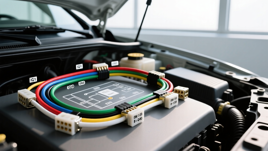
Introduction to Toyota's Electrical Architecture
Toyota's electrical systems are globally renowned for their longevity and logical design. However, when a fault occurs, navigating the Factory Service Manual (FSM) requires fluency in their specific schematic language. Unlike some domestic manufacturers that spell out wire colors or use complex alphanumeric string codes, Toyota relies on a strict, standardized abbreviation system for wire colors and metric cross-sectional areas. For an automotive technician or DIY enthusiast, misunderstanding a single letter in a Toyota wiring diagram can lead to hours of misdiagnosis, back-probing the wrong circuits, or worse, causing a short to ground that damages a sensitive control module.
This complete walkthrough will decode Toyota wiring diagram color codes, explain the crucial difference between base and tracer colors, convert metric wire sizing to AWG, and trace a real-world engine management circuit from the battery to the Engine Control Unit (ECU). Whether you are diagnosing a parasitic draw on a 4Runner or tracing a missing IGT (Ignition Trigger) signal on a Camry, mastering these codes is your first step to an accurate repair.
The Foundation: Reading Toyota Wire Color Abbreviations
In Toyota wiring schematics, wire colors are represented by one or two letters. If a wire is a solid color, it is represented by a single letter. If the wire has a tracer (a stripe running down the length of the wire insulation), it is represented by two letters. It is vital to understand that Toyota uses specific abbreviations that sometimes differ from standard English color names (for example, using 'L' for Blue and 'V' for Violet/Purple).
| Abbreviation | Color | Common Application |
|---|---|---|
| B | Black | Grounds, Switched Power |
| W | White | Main Power Feeds, +B |
| R | Red | Constant Battery Power, Airbag |
| L | Blue | Sensor Signals, CAN-Low |
| G | Green | Injector Controls, Lighting |
| V | Violet (Purple) | Audio, Data Lines, CAN-High |
| Y | Yellow | Alternator Sense, Ignition |
| BR | Brown | Grounds, Sensor Returns |
| GR | Gray | Shielding, Sensor Signals |
| SB | Sky Blue | Transmission Solenoids |
| LG | Light Green | O2 Sensor Heaters, Relays |
| BE | Beige | Interior Lighting, HVAC |
| O | Orange | Dome Lights, Memory Power |
Decoding the Stripe: Base Color vs. Tracer Color
The most common mistake technicians make when reading Toyota diagrams is reversing the base color and the tracer color. In Toyota's nomenclature, the first letter (or first two letters) always represents the base color of the wire insulation. The second letter represents the tracer (stripe) color.
For example, a wire labeled L-Y is a Blue wire with a Yellow stripe. A wire labeled Y-L is a Yellow wire with a Blue stripe. These two wires are entirely different circuits and will often route to completely different connectors or pins on the ECU. When using a digital multimeter (DMM) to pierce a wire or back-probe a connector in a dark engine bay, verifying the base color versus the tracer color is critical to ensuring you are testing the correct circuit.
Metric Cross-Section vs. AWG: Sizing Toyota Wires
As a Japanese manufacturer, Toyota designs its wiring harnesses using Japanese Industrial Standards (JIS), which specify wire cross-sectional area in square millimeters (mm²) rather than the American Wire Gauge (AWG) system. The FSM will display the wire size directly next to the color code, usually formatted as Color-Size (e.g., W-B 1.25). To properly select replacement wire, perform voltage drop calculations, or choose the correct crimp terminal, you must convert mm² to AWG.
| Toyota Metric (mm²) | Equivalent AWG | Typical Use Case |
|---|---|---|
| 0.3 mm² | 22 AWG | Low-current sensor signals, CAN bus |
| 0.5 mm² | 20 AWG | ECU triggers, injector pulses, logic grounds |
| 0.85 mm² | 18 AWG | Relay coils, interior lighting, small solenoids |
| 1.25 mm² | 16 AWG | Switched power feeds, fuel injectors, blower motors |
| 2.0 mm² | 14 AWG | Headlights, power windows, EFI main relays |
| 3.0 mm² | 12 AWG | High-current grounds, ABS pump feeds |
| 5.0 mm² | 10 AWG | Main alternator outputs, starter solenoid feeds |
| 8.0 mm² | 8 AWG | Main battery to fuse block feeds |
For authoritative standards on automotive wire gauge and insulation thickness, technicians can refer to the SAE J1128 specification, which outlines the strict requirements for low-tension automotive cable insulation that Toyota's OEM suppliers (like Sumitomo and Yazaki) adhere to.
Complete Walkthrough: Tracing a 2GR-FE Fuel Injector Circuit
To put these color codes and sizing metrics into practice, let's walk through a diagnostic trace of a fuel injector circuit on a widely used Toyota 3.5L V6 (2GR-FE) engine. We will trace the circuit from the power source, through the injector, and back to the ECU.
Step 1: The Power Feed and EFI Relay
The fuel injectors require a constant 12V reference when the ignition is in the 'ON' position. This power originates at the battery, passes through the main fusible link, and enters the EFI (Electronic Fuel Injection) Relay located in the engine bay fuse block. According to the wiring diagram, the output side of the EFI Relay feeds the injectors via a wire coded W-B 1.25.
- W-B: White base color with a Black tracer stripe.
- 1.25: 1.25 mm² cross-section (equivalent to 16 AWG).
This W-B wire routes to a junction block and splits into six separate wires, one for each injector. At the injector connector (let's look at Cylinder 1, connector ID E4), Pin 1 receives this W-B 1.25 wire. If you are using a DMM to check for power at the injector harness with the key on, engine off (KOEO), you should see battery voltage (approx. 12.4V) between Pin 1 (W-B) and a known good engine ground.
Step 2: The Injector Connector and ECU Ground Trigger
Toyota fuel injectors are ground-switched. The ECU completes the circuit by providing a pulsed ground path. The wire leaving Pin 2 of the Cylinder 1 injector connector is coded P-B 0.5.
- P-B: Pink base color with a Black tracer stripe (Note: Toyota occasionally uses 'P' for Pink in specific engine harnesses, though it is less common in the general chassis manual; always verify against the specific model year FSM).
- 0.5: 0.5 mm² cross-section (equivalent to 20 AWG).
This thinner 20 AWG wire routes directly to the ECU connector (Connector ID E8), terminating at Pin #12. When the ECU commands fuel delivery, it internally grounds this P-B wire. If an injector is not firing, a technician can use a logic probe or oscilloscope on this P-B wire to verify if the ECU is successfully pulling the circuit to ground, or if there is an open circuit in the 0.5 mm² wire between the ECU and the injector harness.
Navigating Junction Blocks (J/B) and Splice Packs
One of the most confusing aspects of Toyota wiring diagrams for beginners is the presence of Junction Blocks (J/B) and Wire-to-Wire Splice Packs. Toyota rarely runs a single continuous wire from a relay to six different components. Instead, a single heavy-gauge wire will enter a J/B, and the diagram will show an internal schematic of how that power is distributed to multiple lighter-gauge wires inside the block.
If your wiring diagram shows a solid black dot where two wires intersect, that is a physical splice pack (often encased in heat-shrink tubing and taped inside the main harness loom). If the intersection shows a 'bridge' or routes through a boxed grid, it represents a Junction Block or Connector Block. When diagnosing a dead circuit where power leaves a relay but never reaches the component, the J/B is a prime suspect for internal corrosion or pushed-out pins, especially in vehicles exposed to heavy road salt or coastal humidity. Detailed diagrams and connector locations for these blocks are available through the Toyota TIS (Technical Information System) portal.
Real-World Diagnostic Failure Modes
Understanding the color codes allows you to quickly isolate the exact wire to test for common Toyota-specific failure modes:
- Ground Point Corrosion (E1 / E01): Toyota separates high-current grounds (like injector returns) from low-current logic grounds (like MAF sensor returns). A corroded body ground point (e.g., Z1 or IE1) will often cause a cascade of seemingly unrelated sensor codes. Always voltage-drop test the brown (BR) or black (B) ground wires back to the battery negative terminal.
- Capillary Action in Sensor Pigtails: If a sensor like the Mass Air Flow (MAF) or an O2 sensor fails and is exposed to moisture, fluid can wick up the wires (often Light Green or Gray) inside the insulation via capillary action, eventually corroding the ECU pins. If you see green crust on an ECU pin, trace the wire color back to the sensor and cut the pigtail open to check for hidden internal corrosion.
- EFI Relay Contact Burn: The White (W) or White-Black (W-B) power feeds passing through the EFI relay carry significant amperage. Over time, the internal contacts of the Denso relay can pit and burn, causing a voltage drop. Always perform a loaded voltage drop test across the relay terminals rather than just checking for open-circuit voltage.
Essential Tools and Best Practices for Circuit Tracing
To properly diagnose circuits using Toyota wiring diagram color codes, you must avoid piercing wires with test lights or standard DMM probes, which can compromise the JIS-compliant insulation and lead to future copper oxidation. Instead, utilize high-quality T-pins or dedicated back-probe pins to test at the rear of the connector cavities. Resources like AutoShop101 provide excellent supplemental training on back-probing Toyota waterproof connectors without damaging the silicone weatherpack seals.
By mastering the base/tracer color rules, converting metric wire sizes accurately, and understanding how Toyota routes power through Junction Blocks, you can transform a complex, intimidating factory wiring schematic into a clear, logical roadmap for any electrical diagnosis.