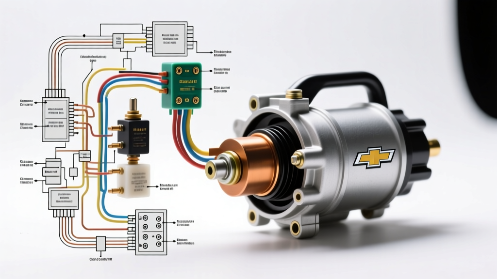
Evolution of the Chevrolet Starter Circuit
When analyzing a modern Chevrolet starter wiring diagram, technicians must recognize the paradigm shift from simple analog loops to multiplexed, module-controlled architectures. Early Gen I Small Block and Mark IV Big Block engines utilized a direct, high-current path from the ignition switch directly to the starter solenoid's 'S' terminal. However, modern platforms—ranging from Gen III/IV LS Vortec engines to the Gen V LT Direct Injection family—rely on a complex control side governed by the Body Control Module (BCM), Powertrain Control Module (PCM), and Transmission Range (TR) sensors. Understanding this bifurcation between the high-current cranking path and the low-current control logic is critical for accurate no-crank diagnostics.
High-Current Architecture: Battery to Solenoid
The primary cranking circuit is responsible for delivering the massive amperage required to overcome engine compression and mechanical friction. A standard 5.3L Vortec or 6.2L LT V8 requires between 150 to 250 amps during initial cranking, with peak stall currents briefly exceeding 400 amps. The wiring diagram for this segment is deceptively simple but highly unforgiving of resistance.
Cable Sizing and Termination Standards
According to SAE J1128 standards for low-tension primary cable, battery-to-starter cables must minimize voltage drop under extreme thermal and electrical loads. Chevrolet typically deploys 2 AWG copper cabling for standard passenger vehicles and light-duty trucks (e.g., Silverado 1500). For heavy-duty applications (Silverado 2500HD/3500HD with Duramax diesels), 1/0 AWG or even 2/0 AWG cables are mandated.
- Termination: Factory cables utilize closed-end copper lugs crimped with a hex-die. Replacement cables must use adhesive-lined heat shrink to prevent galvanic corrosion at the strand-to-lug interface.
- Routing: Cables must maintain a minimum 3-inch clearance from exhaust manifolds to prevent insulation meltdown, a common failure point on aftermarket LS swaps.
The Control Side: Relay Logic and PCM Integration
On modern Chevrolet vehicles, the ignition switch no longer carries the solenoid pull-in current. Instead, turning the key to 'CRANK' (or pressing the start button) sends a low-current signal to the BCM. The BCM verifies the Passlock/PASS-Key III immobilizer data and the PRNDL status via the CAN bus. Once validated, the BCM requests a crank from the ECM/PCM, which then provides the ground path for the starter relay coil.
ISO Mini Relay Pinout Matrix
The starter relay, typically located in the Underhood Electrical Center (UEC), is a standard ISO mini relay. Understanding its pinout is essential when tracing a Chevrolet starter wiring diagram.
| Pin | Function | Wire Gauge | Circuit Description |
|---|---|---|---|
| 30 | Power Feed | 10 AWG | Constant B+ from the UEC main fuse (typically 30A or 40A). |
| 87 | Output to Solenoid | 12 AWG | Switched 12V feed to the starter solenoid 'S' terminal. Often Yellow or Gray. |
| 86 | Coil Power | 14 AWG | Ignition/Crank voltage feed from the BCM or IGN fuse. |
| 85 | Coil Ground | 14 AWG | PCM-controlled ground. The PCM completes the circuit only when security and neutral safety parameters are met. |
Solenoid Terminal Identification
The starter solenoid acts as both a heavy-duty contactor and a mechanical actuator for the Bendix drive pinion. Misidentifying terminals on the starter is a frequent cause of parasitic draws or immediate fuse blowouts.
| Terminal | Designation | Hardware | Connection & Torque Spec |
|---|---|---|---|
| BAT | B+ Input | 3/8" or 5/16" Stud | Main battery cable (2 AWG). Torque: 80-100 in-lbs. Warning: Overtorqing cracks the phenolic cap. |
| S | Start/Pull-in | 1/4" Male Spade | Relay Pin 87 output. Receives 12V to energize the pull-in and hold-in windings. |
| I | Ignition Bypass | 1/4" Spade or R-Post | Used on older HEI systems to bypass the ballast resistor during cranking. Unused on modern LS/LT platforms. |
Advanced Voltage Drop Diagnostics
Relying on a multimeter's continuity beep or resistance (Ohms) setting is insufficient for diagnosing high-current starter circuits. A single strand of copper can show continuity but will collapse under a 200-amp load. As outlined by the diagnostic procedures at AA1Car's Technical Library, dynamic voltage drop testing is the only valid method for assessing circuit health.
Step-by-Step Control Circuit Voltage Drop
If the starter relay is not clicking, perform a voltage drop test on the control side while an assistant holds the key in the CRANK position:
- Test Pin 86 (Coil Power): Place the red multimeter lead on the battery positive post and the black lead on Relay Pin 86. A reading above 0.5V indicates high resistance in the IGN feed circuit or a faulty BCM output.
- Test Pin 85 (PCM Ground): Place the red lead on Relay Pin 85 and the black lead on the battery negative post. A reading above 0.2V indicates a corroded PCM ground splice pack (commonly located near the left cylinder head on Silverados) or an internal PCM driver fault.
- Test Pin 87 to Solenoid 'S': Place the red lead on the battery positive post and the black lead on the solenoid 'S' spade terminal during a crank attempt. Any reading over 0.5V confirms excessive resistance in the engine harness, often due to terminal fretting at the UEC connector.
Platform-Specific Failure Modes
Chevrolet platforms exhibit unique electrical failure modes tied to their specific chassis and engine bay layouts. Familiarity with these will drastically reduce diagnostic time.
Gen III/IV LS Engine Heat Soak
On vehicles like the C5/C6 Corvette, Camaro, and Pontiac GTO, the starter is nestled tightly against the exhaust manifold and oil pan. The phenolic insulation inside the solenoid degrades over time due to extreme thermal cycling. When the engine is hot, the solenoid's internal resistance increases, requiring more amperage to pull the plunger. If the control wire (12 AWG) suffers even a minor voltage drop, the solenoid will chatter or fail to engage. Fix: Install a dedicated 30-amp relay upgrade kit utilizing 10 AWG wire directly from the battery to the 'S' terminal, triggered by the OEM harness.
GMT900 Silverado/Sierra Ground Degradation
The 2007-2013 GMT900 Chevrolet trucks suffer from a notorious ground strap failure. The primary engine-to-frame ground strap (typically a braided 1/0 AWG cable located near the passenger side motor mount or lower bellhousing) corrodes internally due to exposure to road salt and water ingress. Because the starter solenoid relies on the engine block for its return path to the battery negative, a degraded block ground will result in a slow-crank or no-crank condition, often accompanied by erratic PCM behavior or CAN-bus communication codes (U0100). Diagnostic Tip: Use a heavy-duty jumper cable to bridge the alternator casing directly to the battery negative terminal. If the engine cranks normally, the block ground strap must be replaced or supplemented with a secondary 2 AWG ground cable.
Installation and Torque Specifications
When replacing the starter or rebuilding the wiring harness, adhering to OEM torque specifications is non-negotiable to prevent mechanical fatigue and electrical arcing. For comprehensive torque and pinout references, technicians should consult the Standard Motor Products Technical Library or OEM service information.
- Starter Mounting Bolts (M10x1.5): 35-50 lb-ft. (Use threadlocker if specified by the block material; aluminum blocks require careful thread engagement).
- Solenoid BAT Nut: 80-100 in-lbs (Do NOT exceed, or the phenolic cap will fracture, leading to moisture ingress and internal shorting).
- Ring Terminal Crimps: Must be performed with a calibrated hex-crimp tool, followed by 3M adhesive-lined heat shrink applied at 250°F to ensure a watertight seal.
By mastering both the high-current physical routing and the low-current multiplexed logic of the Chevrolet starter wiring diagram, technicians can confidently diagnose and resolve complex no-crank scenarios on any GM platform.