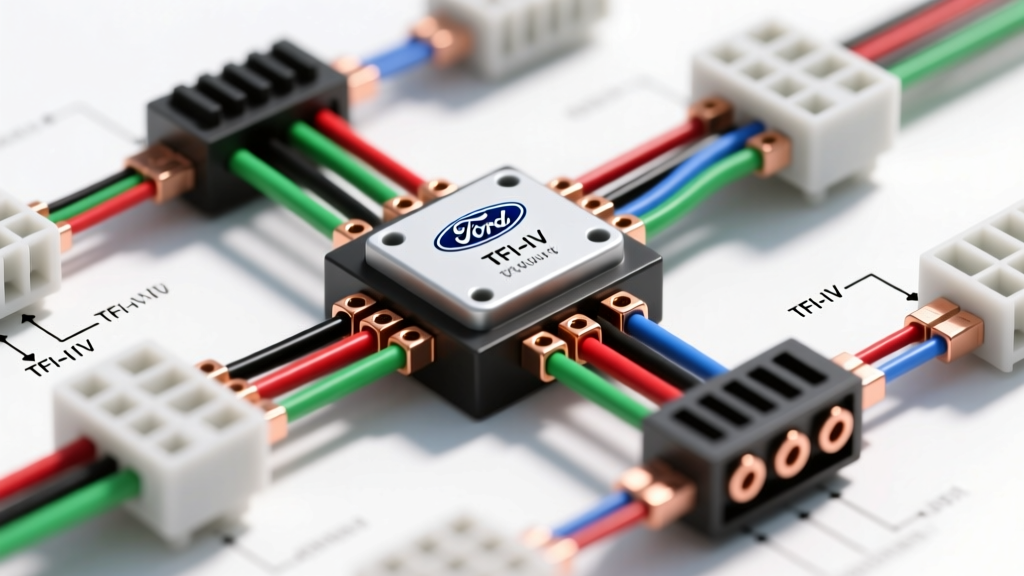
Demystifying the Ford Ignition Module Wiring Diagram
When you first look at a Ford ignition module wiring diagram, the web of colors, pin numbers, and acronyms can feel overwhelming. For beginners and DIY mechanics transitioning from older breaker-point systems to electronic ignition, the schematic looks like a foreign language. However, understanding these fundamentals is the key to diagnosing no-spark conditions, fixing stalling issues, and performing engine swaps on classic Foxbody Mustangs, F-150 trucks, and Rangers.
This guide breaks down the legendary Ford TFI-IV (Thick Film Integrated) ignition system. We will translate the factory schematic into plain English, detail the exact wire colors and AWG sizes, and provide actionable multimeter testing procedures to get your engine firing reliably.
What is the TFI-IV Ignition System?
Introduced in the mid-1980s and used well into the 1990s, the TFI-IV module is a solid-state switch that controls the primary circuit of the ignition coil. Unlike older modules that were entirely self-contained, the TFI-IV works in tandem with the Ford EEC-IV (Electronic Engine Control) computer. The distributor contains a stator (reluctor) that sends a raw signal to the module. The module then communicates with the ECU to determine exact spark timing, ultimately firing the coil.
According to automotive electrical standards outlined by SAE International, modern electronic ignition systems rely on precise low-voltage signal switching to manage high-voltage secondary outputs. The TFI-IV is a textbook example of this, utilizing a 6-pin connector to manage power, ground, signal input, and coil switching.
The 6-Pin Connector: Pinout and Wire Color Chart
The most critical step in reading any Ford ignition module wiring diagram is identifying the 6-pin harness connector. Below is the standard pinout for the most common Push-Start TFI-IV systems found on 5.0L, 4.9L, and 2.3L engines.
| Pin | Function | Standard Wire Color | AWG Size | Signal Type |
|---|---|---|---|---|
| 1 | IGN (Power In) | Red/Light Green | 14 AWG | 12V DC (Run/Start) |
| 2 | Ground | Black | 14 AWG | Chassis/Battery Ground |
| 3 | PIP (Profile Ignition Pickup) | Gray/Orange | 18 AWG | 5V Square Wave (Input) |
| 4 | SPOUT (Spark Output) | Yellow/Light Green | 18 AWG | 5V Logic (ECU Input) |
| 5 | Coil (-) / TACH | Dark Green/Orange | 16 AWG | 12V Switched to Ground |
| 6 | IDM (Ignition Diagnostic Monitor) | White/Light Blue | 18 AWG | Pulse Signal (to ECU) |
Reading the Schematic: A Beginner's Translation
Let us break down the diagram circuit by circuit so you understand why the wires are routed the way they are.
1. The Power and Ground Circuit (Pins 1 & 2)
The module requires a solid 12V source during both the 'Run' and 'Start' key positions. This is fed through a 14 AWG Red/Light Green wire from the ignition switch. If your vehicle cranks but dies the moment you release the key from 'Start' to 'Run', you likely have a broken wire or faulty ignition switch interrupting Pin 1. Pin 2 (Black, 14 AWG) grounds the module. Expert Tip: The TFI module relies on its physical mounting bracket for secondary grounding, but Pin 2 is the primary logic ground. Never mount a TFI module to a painted surface without a dedicated ground wire.
2. The PIP Signal (Pin 3)
PIP stands for Profile Ignition Pickup. As the distributor shaft spins, the stator ring generates a 5V square wave signal. This travels via an 18 AWG Gray/Orange wire to Pin 3. The TFI module reads this raw engine position data and passes it to the ECU. If you have no PIP signal, the ECU will not fire the fuel injectors, resulting in a no-start condition with no spark and no fuel.
3. The SPOUT Logic (Pin 4)
SPOUT (Spark Output) is where the magic of computer-controlled timing happens. The ECU calculates the ideal ignition timing based on coolant temperature, load, and RPM. It sends a 5V logic signal back to the TFI module via the 18 AWG Yellow/Light Green wire. This tells the module exactly when to fire the coil. When you set your base timing with a timing light, you must unplug the SPOUT connector to remove the ECU's advance curve from the equation.
4. Coil Switching (Pin 5)
Pin 5 connects to the negative terminal of the ignition coil. The TFI module acts as a high-speed switch, grounding this circuit to build a magnetic field in the coil, and then breaking the ground to collapse the field and create a high-voltage spark. This wire also typically branches off to the tachometer on your dashboard.
Push-Start vs. CCD Systems
When consulting a comprehensive automotive ignition guide, you will notice Ford used two variations of the TFI system. It is vital to know which one you are wiring:
- Push-Start TFI: The module calculates the dwell time (how long the coil charges) internally. This is the most common system on 1980s vehicles.
- CCD (Computer Controlled Dwell): Introduced in the early 90s, the ECU takes over dwell calculation to optimize coil saturation at high RPMs. The wiring diagram is nearly identical, but the internal module logic and ECU programming differ. Swapping a Push-Start module into a CCD harness will result in weak spark and misfires at high RPM.
Real-World Troubleshooting and Multimeter Testing
Before replacing parts, use a digital multimeter (DMM) to verify the wiring diagram's integrity.
Testing the PIP Signal
Set your DMM to DC Volts. Back-probe Pin 3 (Gray/Orange) with the key in the 'Run' position. Slowly bump the engine over or turn the crank by hand. You should see the voltage snap cleanly between 0.0V and 5.0V. If the voltage floats around 2.5V or drops to 1.2V, your distributor stator is failing or the wiring is shorted.
Testing the Coil Circuit
Connect a test light between the battery positive terminal and Pin 5 (Dark Green/Orange). Crank the engine. The test light should blink rapidly, indicating the module is successfully switching the coil ground. If the light stays solidly illuminated, the module is shorted internally or the coil primary winding is open.
Critical Installation Mistakes to Avoid
Even with a perfect wiring diagram, physical installation errors destroy thousands of Ford ignition modules every year. Avoid these common beginner pitfalls:
- Forgetting Thermal Paste: The TFI module generates significant heat. You must apply a generous layer of dielectric silicone heat-sink compound between the back of the module and its mounting bracket. Without it, the module will overheat and fail within a few hundred miles.
- Using the Wrong Dielectric Grease: Heat sink compound is designed to transfer heat. Standard bulb socket dielectric grease is an insulator and will trap heat, accelerating module death.
- Soldering Signal Wires: While soldering is great for power wires, the 18 AWG PIP and SPOUT signal wires are highly susceptible to heat damage and vibration-induced cracking near the connector. Use high-quality, adhesive-lined heat shrink crimp connectors for harness repairs.
By understanding the fundamental logic behind the Ford ignition module wiring diagram, you transition from simply swapping parts to truly diagnosing the electrical system. Keep this pinout chart in your toolbox, respect the thermal requirements of the module, and you will enjoy years of reliable, high-energy spark.