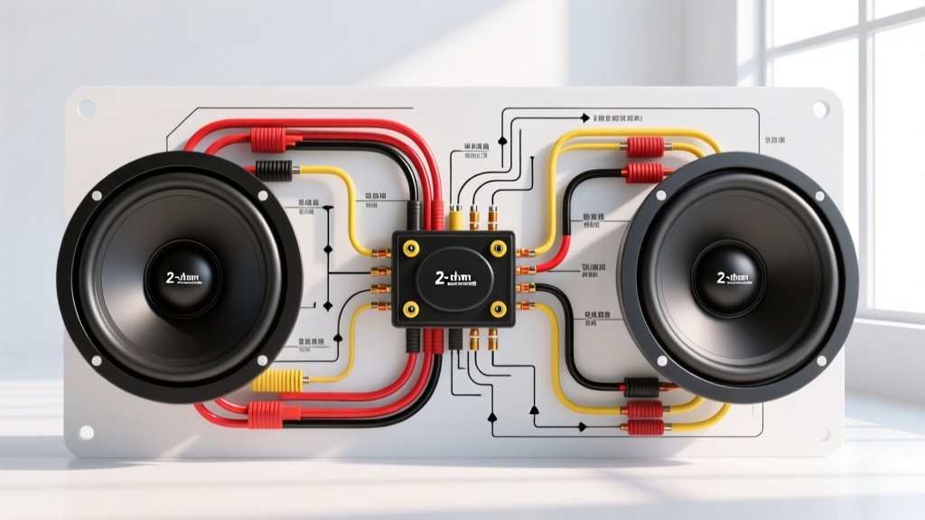
Introduction to DVC Subwoofer Upgrades
Upgrading a vehicle's low-frequency response requires more than just dropping a new enclosure into the trunk; it demands a precise understanding of electrical load management. When planning an audio upgrade, referencing an accurate subwoofer wiring diagram dual 2 ohm configuration is critical to prevent amplifier clipping, thermal shutdown, and alternator strain. Dual Voice Coil (DVC) 2-ohm subwoofers are the undisputed heavyweights of modern mobile audio because they offer unparalleled flexibility in impedance matching. Whether you are wiring a single subwoofer to a high-current Class D monoblock or pairing two subwoofers to a multi-channel amplifier, manipulating the series and parallel pathways dictates the final ohm load presented to the amplifier's output terminals.
Unlike Single Voice Coil (SVC) models that lock you into a fixed impedance, DVC 2-ohm drivers feature two independent winding coils, each with a nominal impedance of 2 ohms. This architecture allows installers to wire the coils in series (yielding 4 ohms), in parallel (yielding 1 ohm), or combine multiple subwoofers in a series-parallel matrix to achieve a stable 2-ohm or 4-ohm final load. This guide breaks down the exact wiring pathways, AWG power specifications, and termination standards required for a professional-grade installation.
Understanding Impedance: DC Resistance vs. AC Impedance
Before cutting wire, it is vital to distinguish between DC Resistance (Re) and AC Impedance (Ze). When you place a digital multimeter (DMM) across a single 2-ohm voice coil, the meter will not read exactly 2.0 ohms. According to Thiele/Small parameters, the DC resistance (Re) is typically 75% to 85% of the nominal AC impedance. Therefore, a healthy 2-ohm coil will read between 1.5 and 1.7 ohms on your multimeter. If your DMM reads 0.1 ohms, the coil is shorted; if it reads infinite (OL), the coil is blown. Understanding this baseline is crucial for troubleshooting amplifier protection modes post-installation. For deeper insights into mobile audio electrical standards, refer to the CTA-2015 Mobile Audio Amplifier Power Rating standard, which dictates how manufacturers must test and advertise RMS wattage at specific impedance loads.
Subwoofer Wiring Diagram Dual 2 Ohm: The Configuration Matrix
Because we cannot embed visual schematics directly into this text interface, we have mapped the exact current pathways for the most common DVC 2-ohm configurations. Always use Oxygen-Free Copper (OFC) speaker wire, minimum 12 AWG, for the internal enclosure wiring to minimize resistance and maximize the amplifier's damping factor.
Single Subwoofer Configurations
1. Series Wiring (Final Load: 4 Ohms)
Ideal for amplifiers that are not 1-ohm stable or for maximizing voltage swing on high-impedance Class AB amps.
Pathway: Amplifier Positive (+) ➔ Subwoofer Coil 1 Positive (+). Coil 1 Negative (-) ➔ Subwoofer Coil 2 Positive (+) [This is the series jumper]. Coil 2 Negative (-) ➔ Amplifier Negative (-).
2. Parallel Wiring (Final Load: 1 Ohm)
Designed for high-current Class D monoblocks certified for 1-ohm stability. This configuration maximizes current draw and RMS output.
Pathway: Amplifier Positive (+) splits via a distribution block to both Coil 1 (+) and Coil 2 (+). Amplifier Negative (-) splits to both Coil 1 (-) and Coil 2 (-).
Dual Subwoofer Configurations (The Sweet Spot)
When installing two DVC 2-ohm subwoofers, the Series-Parallel configuration is the industry standard for achieving a 2-ohm final load, which perfectly matches the peak efficiency sweet spot of most modern Class D amplifiers.
| Configuration | Coil Wiring (Per Sub) | Sub-to-Sub Wiring | Final Amp Load | Amp Requirement |
|---|---|---|---|---|
| Series-Parallel | Series (4 ohms per sub) | Parallel | 2 Ohms | 2-Ohm Stable Monoblock |
| Parallel-Series | Parallel (1 ohm per sub) | Series | 2 Ohms | 2-Ohm Stable Monoblock |
| All Series | Series (4 ohms per sub) | Series | 8 Ohms | Any (Low Power Output) |
| All Parallel | Parallel (1 ohm per sub) | Parallel | 0.5 Ohms | Specialty 0.5-Ohm Stable Amp |
Mapping the Series-Parallel Pathway (2-Ohm Final Load):
1. Wire the two coils on Subwoofer A in series (Yielding 4 ohms).
2. Wire the two coils on Subwoofer B in series (Yielding 4 ohms).
3. Connect the positive terminal of Subwoofer A and the positive terminal of Subwoofer B together, then run a single 8 AWG OFC wire to the Amplifier Positive (+).
4. Connect the negative terminal of Subwoofer A and the negative terminal of Subwoofer B together, then run a single 8 AWG OFC wire to the Amplifier Negative (-).
For visual learners, cross-referencing this pathway with a visual subwoofer wiring diagram resource can help verify terminal polarity before applying power.
Power, Ground, and Signal Wire AWG Specifications
The subwoofer wiring diagram dual 2 ohm is only half the battle; the power delivery network must support the current demands of the chosen impedance load. As impedance drops, current (Amperage) increases according to Ohm's Law (I = P/V). A 1000W RMS amplifier operating at 1 ohm will pull significantly more current from the vehicle's electrical system than one operating at 4 ohms, due to the reduced efficiency and increased heat dissipation at lower impedances.
| Total RMS Wattage | Recommended Power/Ground AWG | Fuse Rating (ANL/Class T) | Speaker Wire AWG |
|---|---|---|---|
| 0 - 400W | 4 AWG OFC | 40A - 60A | 16 AWG - 14 AWG |
| 400 - 800W | 1/0 AWG OFC | 80A - 120A | 14 AWG - 12 AWG |
| 800 - 1500W | 2/0 AWG OFC | 150A - 200A | 12 AWG - 10 AWG |
| 1500W - 3000W+ | 3/0 AWG or Dual 1/0 Runs | 250A - 400A Class T | 10 AWG - 8 AWG |
Always adhere to SAE J1128 standards when selecting battery cable for high-current mobile audio applications. Avoid Copper-Clad Aluminum (CCA) wire, as its higher resistance leads to voltage drop, which in turn starves the amplifier's power supply capacitors and causes subwoofer clipping at high excursion limits.
Termination Standards and Vibration Resistance
Automotive environments are subjected to constant vibration, thermal cycling, and humidity. Soldering speaker wire directly to subwoofer terminals is a common DIY mistake; the rigid solder joint creates a fulcrum point that can snap the flexible tinsel lead inside the voice coil former over time. Instead, use high-strand-count OFC wire terminated with heavy-duty ring terminals or spade connectors. For amplifier set-screw terminals, strip the wire cleanly, twist the strands tightly, and insert directly into the block without tinning the wire with solder, as solder cold-flows under pressure, leading to a loose connection and subsequent arcing.
Troubleshooting Amplifier Protection Modes
If your amplifier immediately enters protection mode upon powering on, the issue is almost always tied to an impedance mismatch or a short circuit. Follow this diagnostic tree:
- Disconnect all speaker wire from the amp. Turn the head unit on. If the amp powers up normally (green/blue power LED), the internal power supply and vehicle charging system are fine. The fault lies in the subwoofer wiring.
- Test the Subwoofer Load. Set your DMM to the lowest ohm setting (usually 200Ω). Measure across the speaker wires at the amplifier end. If you wired for a 2-ohm load, your meter should read approximately 1.6 to 1.8 ohms (Re). If it reads 0.0 or 0.1 ohms, you have a short circuit—likely a pinched wire grounding to the vehicle chassis or a blown coil.
- Check for Thermal Protection. If the amp plays for 10 minutes and then shuts off, the impedance may be too low for the amplifier's thermal dissipation capabilities. Running a 1-ohm load on an amplifier rated only for 2-ohm minimums will cause the output MOSFETs to overheat, triggering the thermal protection circuit. Verify your wiring diagram and rewire to a higher impedance if necessary.
By strictly following the correct subwoofer wiring diagram dual 2 ohm pathways and utilizing proper AWG OFC cabling, you ensure maximum acoustic output, optimal damping factor, and long-term reliability of your mobile audio investment.