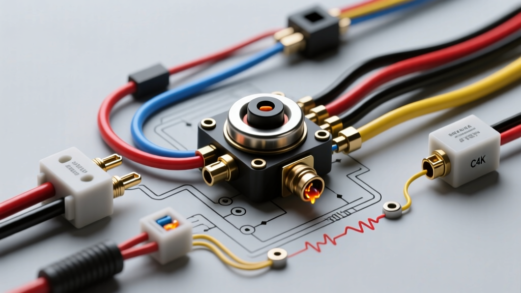
The Anatomy of a Relay-Less Train Horn Circuit
An air horn train horn wiring diagram without relay represents a direct series circuit where the full electrical load of the horn’s solenoid valves passes directly through the dashboard-mounted actuation switch. In this schematic, the current path flows from the 12V battery positive terminal, through an inline MAXI fuse, into the dashboard SPST (Single Pole Single Throw) rocker switch, out to the 12V DC solenoid valve coil, and finally to the chassis ground.
While this direct-wire diagram is electrically simple and often attempted by novice installers to save on components, it fundamentally ignores the physics of inductive loads. Train horn solenoids—such as those used in Nathan AirChime replicas or VIAIR onboard air systems—are highly inductive. They require a massive inrush current (often 30 to 45 amps) to pull the internal plunger and open the air valve, followed by a lower continuous holding current (15 to 20 amps). Furthermore, when the switch is released, the collapsing magnetic field generates a severe reverse voltage spike (back-EMF) that arcs across the switch contacts. This troubleshooting guide provides a step-by-step diagnostic flow to identify and resolve the inevitable failures caused by relay-less train horn wiring.
Step-by-Step Troubleshooting Flow
When a direct-wire train horn system fails, the symptoms almost always manifest as thermal damage to the switch, weak horn output, or continuous air hissing. Follow this sequential diagnostic flow to isolate the fault.
Phase 1: Visual and Thermal Inspection (The Melted Switch Fault)
The most common failure in an air horn train horn wiring diagram without relay is the catastrophic melting of the dashboard switch housing. Standard automotive SPST rocker switches are typically rated for 20 amps. However, according to Littelfuse Rocker Switch Derating Guidelines, switches must be derated by up to 50% when controlling inductive loads like solenoids and motors due to contact arcing.
- Step 1: Remove the dash switch and inspect the rear spade terminals. Look for brown discoloration, melted plastic housing, or oxidized (blackened) brass terminals.
- Step 2: Check the wire insulation on the 10 AWG or 12 AWG pigtails connected to the switch. If the insulation is brittle or shrunk back from the crimp barrel, the switch has been operating at unsafe thermal limits.
- Diagnosis: If melting is present, the switch has been destroyed by inductive arcing and inrush current overload. The relay-less diagram must be abandoned and upgraded to a relay-driven schematic.
Phase 2: Voltage Drop Testing (The Weak Horn / Chatter Fault)
If the horn sounds weak, the pitch drops significantly, or the solenoid produces a rapid 'chattering' noise, the issue is severe voltage drop. Solenoids require a minimum of 11.5V to fully seat the internal plunger. If voltage drops below this threshold, the plunger hovers, causing the valve to rapidly open and close.
- Step 1: Set your digital multimeter (DMM) to DC Volts. Connect the black probe to a known good chassis ground and the red probe to the battery positive terminal. Verify baseline voltage (should be 12.4V - 12.6V with engine off, 13.8V - 14.2V with engine running).
- Step 2: Have an assistant press and hold the horn button. Move the red probe to the input terminal of the dash switch. Note the voltage.
- Step 3: Move the red probe to the output terminal of the dash switch (the wire heading to the solenoid).
- Step 4: Finally, probe the positive terminal directly on the solenoid valve coil while the button is held.
- Diagnosis: A voltage drop greater than 0.5V across the switch indicates internal contact resistance (failing switch). A drop greater than 1.0V between the switch output and the solenoid terminal indicates undersized wire gauge. For a 20-amp continuous draw over a 12-foot round-trip run, 10 AWG copper wire will exhibit a voltage drop of approximately 0.24V. If you are using 14 AWG or 16 AWG wire in a relay-less setup, the voltage drop will exceed 1.5V, guaranteeing solenoid chatter.
Phase 3: Solenoid Hissing and Back-EMF Analysis
If the train horn continues to hiss or leak air after the dash switch is released, the solenoid valve is stuck open. In a relay-less diagram, this is rarely a mechanical debris issue and almost always an electrical welding issue.
- Step 1: Disconnect the 12V feed wire at the solenoid. If the hissing stops immediately upon disconnection, the solenoid is still receiving power despite the switch being in the 'OFF' position.
- Step 2: Inspect the dash switch contacts. The back-EMF spike generated when the inductive coil collapses can exceed 100 volts for a fraction of a millisecond. This spike causes a plasma arc across the dash switch contacts, effectively micro-welding them together.
- Diagnosis: The switch is internally welded closed due to the lack of a flyback diode or a relay to absorb the inductive kickback. Refer to VIAIR Corporation Solenoid Valve Specifications for maximum allowable switching cycles without arc suppression.
Direct-Wire Train Horn Specification & Failure Matrix
The following table outlines the electrical realities of wiring common train horn solenoids directly through a dashboard switch, highlighting why the air horn train horn wiring diagram without relay is inherently flawed for long-term reliability.
| Solenoid Type | Inrush Current (Peak) | Continuous Hold Current | Min Wire Gauge (Direct) | Switch Failure Mode (Relay-Less) |
|---|---|---|---|---|
| 1/2' NPT Standard 12V | 35 - 45 Amps | 15 - 18 Amps | 8 AWG | Contact welding, terminal melting |
| 3/8' NPT Compact 12V | 25 - 30 Amps | 10 - 12 Amps | 10 AWG | Thermal degradation, high resistance |
| Heavy Duty Peterbilt Style | 50+ Amps | 20 - 25 Amps | 6 AWG | Immediate switch destruction, fire hazard |
Correcting the Diagram: Upgrading to a Safe SAE-Compliant Circuit
To permanently resolve the faults identified in the troubleshooting flow above, the relay-less diagram must be converted to a relay-driven schematic. This isolates the high-amperage inductive load from the delicate dashboard switch and the vehicle's interior wiring harness.
Step 1: Select the Proper Relay
Do not use a standard 30A ISO mini relay for train horns. The inrush current will quickly pit and destroy the internal contacts. Select a heavy-duty continuous duty relay, such as a Bosch JD1914 (rated for 40A continuous) or a White-Rodgers 586 series solenoid relay capable of handling 90A inrush spikes. Ensure the relay coil pins (85 and 86) are clearly marked.
Step 2: Implement the Flyback Diode
To protect the new relay's internal contacts and the vehicle's ECU from inductive back-EMF, solder a 1N4007 rectifier diode in parallel with the solenoid coil. The cathode (silver stripe) must point toward the 12V positive feed, and the anode toward the ground. This creates a safe recirculation path for the collapsing magnetic field, eliminating the voltage spike entirely.
Step 3: Rewire the Control and Load Circuits
- Control Circuit (Low Amp): Run 16 AWG wire from a switched 12V ignition source to the dash switch, then to Relay Pin 86. Ground Relay Pin 85 to the chassis. The dash switch now carries less than 0.5 amps.
- Load Circuit (High Amp): Run 8 AWG primary wire directly from the battery positive terminal to a 40A MAXI fuse (compliant with SAE International J553 Standard for Circuit Protectors), then to Relay Pin 30. Run another 8 AWG wire from Relay Pin 87 directly to the solenoid positive terminal. Ground the solenoid negative terminal to the chassis using a 3/8' ring terminal and a star washer to ensure bare metal contact.
Summary
Attempting to utilize an air horn train horn wiring diagram without relay is a diagnostic time bomb. The combination of high inrush current, sustained inductive loads, and severe back-EMF will inevitably destroy dashboard switches and cause dangerous voltage drops. By following this troubleshooting flow, you can accurately diagnose thermal and electrical faults, and subsequently upgrade the system to a safe, relay-driven architecture that guarantees maximum acoustic output and long-term electrical safety.