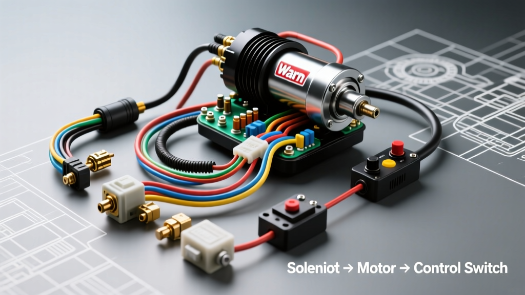
Understanding the Warn Winch Contactor Architecture
When integrating heavy-duty recovery equipment into a vehicle electrical system, understanding the specific wiring diagram Warn winch configurations is critical for both performance and safety. Modern Warn winches (including the VR EVO, Zeon, and M-series) utilize a centralized 4-post contactor pack rather than the older, failure-prone 4-solenoid setups. This contactor acts as a high-amperage relay, bridging the vehicle battery circuit to the series-wound DC motor. Troubleshooting these systems requires a methodical approach, moving from the low-amperage control circuits to the high-current main power feeds. This guide provides a step-by-step troubleshooting flow, complete with AWG specifications, torque values, and voltage drop thresholds aligned with SAE J1128 Low Voltage Primary Cable standards.
OEM Warn Winch Wiring Diagram Reference
Before testing, verify your physical wiring against the standard Warn 4-post contactor schematic. The contactor is typically a Trombetta or Albright unit, depending on the winch series. Below is the standard pinout and wire gauge matrix for a 10,000 to 12,000 lb capacity Warn winch.
| Terminal Post | Function | Warn Wire Color | AWG Size | Connector Type |
|---|---|---|---|---|
| Post A (Top Left) | Motor Lead 1 | Yellow | 2 AWG | 5/16' Ring Terminal |
| Post B (Top Right) | Motor Lead 2 | Black (Blue Stripe) | 2 AWG | 5/16' Ring Terminal |
| Post C (Bottom Left) | Battery Positive (+) | Red | 2 AWG (or 1/0 AWG) | 5/16' Ring Terminal |
| Post D (Bottom Right) | Chassis Ground (-) | Black | 2 AWG (or 1/0 AWG) | 5/16' Ring Terminal |
| Control Spade 1 | 12V+ Coil Feed | Red (Small) | 12 AWG | 1/4' Spade / Inline Fuse |
| Control Spade 2 | IN Trigger | Yellow/Green | 14 AWG | 1/4' Spade |
| Control Spade 3 | OUT Trigger | Green/Black | 14 AWG | 1/4' Spade |
Step-by-Step Troubleshooting Flow
Use the following decision trees to isolate electrical faults. Always use a digital multimeter (DMM) capable of measuring millivolts (mV) and a clamp-style DC ammeter for high-current validation.
Symptom A: Audible Click, But No Motor Rotation
This symptom indicates that the low-amperage control circuit is successfully engaging the contactor coil, but the high-current path is failing to deliver amperage to the motor.
- Verify Battery State of Charge (SoC): Measure battery voltage at the posts. It must read above 12.4V. Winches can draw 300A to 450A under load; a weak battery will cause the contactor to chatter or drop out.
- Perform a Voltage Drop Test (Main Cables): Set your DMM to DC Volts. Place the red probe on the battery positive post and the black probe on Contact Post C. Have an assistant 'bump' the winch IN. A reading greater than 0.2V indicates high resistance (corrosion, undersized AWG, or loose crimp) in the positive cable. Repeat for the ground path (Battery Negative Post to Contact Post D).
- Contactor Bypass Test: Using a heavy-duty jumper cable or a dedicated winch bypass tool, carefully bridge Post C (Battery) and Post A (Motor 1). If the motor spins, the contactor internal contacts are pitted or welded open. Replace the contactor pack.
- Motor Armature Test: If bypassing the contactor yields no movement, the fault lies in the motor. Remove the motor end cap and check the carbon brushes for wear. Brushes should have at least 3/8' of material remaining. Check the commutator for scoring.
Symptom B: Dead System (No Click, No Motor)
A completely dead system points to an open circuit in the main power feed, a blown main breaker, or a failure in the control switch circuit.
- Inspect the Main Circuit Breaker: Warn winches utilize a high-amperage inline breaker (typically 150A to 250A depending on the model) or a fusible link near the battery. Test for continuity across the breaker. If tripped, allow it to cool and reset. If blown, replace with an OEM-specified marine-grade breaker.
- Test the Control Circuit Power: Locate the small red 12 AWG control wire on the contactor spade. Probe this wire with your DMM (black lead to chassis ground). You should read full battery voltage (12.6V). If 0V, trace the red wire back to the battery or ignition-switched fuse block.
- Validate the Remote Switch: Disconnect the 5-pin remote control plug. Using a paperclip or jumper wire, bridge Pin 1 (12V+ Red) to Pin 3 (IN Trigger). If the contactor clicks, the remote switch or wireless receiver is faulty. For detailed remote diagnostics, refer to the official Warn Industries installation manuals.
Symptom C: Winch Powers IN, But Not OUT
This is a classic directional failure, almost always isolated to the control circuit or a single failed solenoid coil within the contactor pack.
- Test the OUT Trigger Wire: Probe the Green/Black (or model-specific OUT trigger) wire at the contactor spade while pressing the OUT button on the remote. You should see a 12V signal. If no signal, the fault is in the remote switch or wiring harness.
- Measure Solenoid Coil Resistance: Disconnect the trigger wire and measure the resistance (Ohms) between the trigger spade and the contactor ground. A healthy coil typically reads between 12 and 18 Ohms. An infinite reading (OL) indicates a burned-out internal coil. The entire contactor must be replaced, as Warn contactors are generally sealed, non-serviceable units.
5-Pin Remote Control Connector Pinout
When diagnosing in-cab control kits or wireless adapters, understanding the 5-pin connector is essential. Damage to these pins is a common cause of erratic winch behavior.
| Pin Number | Wire Color | Function | Diagnostic Check |
|---|---|---|---|
| 1 | Red | 12V+ Constant Power | Check for 12.6V to ground. |
| 2 | Black | Ground Reference | Check for continuity to chassis. |
| 3 | Yellow | IN Trigger (Spool In) | Should receive 12V when IN is pressed. |
| 4 | Green | OUT Trigger (Spool Out) | Should receive 12V when OUT is pressed. |
| 5 | White | Accessory / LED Power | Used for wireless module status LEDs. |
Wire Gauge, Torque, and Routing Specifications
Improper torque and undersized wiring are the leading causes of thermal fires in auxiliary winch installations. Always adhere to the following specifications when rebuilding or repairing a Warn winch harness.
- Main Power Cables: Use only 100% copper, SAE J1128 compliant cable. For runs under 10 feet, 2 AWG is sufficient for up to 12,000 lbs. For runs exceeding 10 feet (e.g., routing to the rear of a long-bed truck or trailer), upgrade to 1/0 AWG to mitigate voltage drop.
- Terminal Crimping: Use a closed-barrel hex crimp tool. Never solder high-current 2 AWG battery lugs; solder can melt and flow under the extreme heat generated by 400A loads, causing the connection to fail catastrophically.
- Stud Torque Specifications: The standard 5/16'-18 threaded studs on Warn contactors are fragile. The required torque is 120 to 140 in-lbs (10 to 12 ft-lbs). Over-torquing will snap the stud from the internal bus bar, destroying the contactor. Under-torquing will cause micro-arcing, melting the plastic casing.
- Dielectric Grease: Apply a heavy coat of marine-grade dielectric grease to all contactor posts and ring terminals to prevent galvanic corrosion, especially in winter environments where road salt is present.
Common Failure Modes & Field Fixes
Water Intrusion in the Motor Housing: Warn motors are sealed, but the breather tube is often overlooked. If the breather tube is routed downward or submerged, water is drawn into the motor housing during cooling cycles. This leads to armature rust and brush binding. Field Fix: Route the breather tube up into the engine bay or frame rail, and use a small piece of open-cell foam over the end to filter debris while allowing airflow.
Control Wire Chafing: The 14 AWG trigger wires are often zip-tied too tightly against the winch fairlead bracket or chassis. Vibration wears through the insulation, causing a short to ground that triggers the winch unexpectedly or blows the inline control fuse. Field Fix: Wrap all control wires in split-loom tubing and secure them with adhesive-lined heat shrink away from moving suspension components.
Authoritative References
For continued education on automotive electrical standards and OEM recovery equipment specifications, consult the following resources: