Introduction: The Economics of Electronic Boost Control
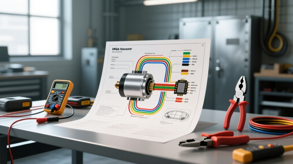
Modern turbocharged engines rely heavily on precision boost control, transitioning away from simple vacuum-referenced wastegates to sophisticated Electronic Wastegate Actuators (EWGA). When technicians and advanced DIYers search for a 4 wire actuator wiring diagram pdf, they are typically dealing with these critical EWGA units found on platforms like the Ford EcoBoost, GM Ecotec, and various European turbocharged powertrains. Unlike a basic 2-wire DC motor, a 4-wire actuator integrates a high-torque DC motor with an internal potentiometer for closed-loop position feedback, managed by a Pulse Width Modulated (PWM) signal from the Powertrain Control Module (PCM).
Misdiagnosing a boost under/over-voltage condition (such as DTC P0299 or P0234) without a proper wiring schematic often leads to unnecessary turbocharger replacements costing upwards of $2,500. By leveraging a factory 4 wire actuator wiring diagram pdf, automotive electrical specialists can isolate the fault to the actuator, the wiring harness, or the PCM driver. This guide provides a comprehensive cost and tool requirements analysis to help you accurately diagnose, test, and repair 4-wire EWGA systems while maximizing your return on diagnostic investment.
Decoding the 4-Wire EWGA Schematic: Pinouts and Wire Colors
To accurately perform voltage drop tests and oscilloscope captures, you must understand the exact pin configuration. While specific OEM wire colors vary by manufacturer and model year, the fundamental architecture of the 4-pin Delphi or Molex sealed connector remains consistent across most late-model applications. Below is the standardized reference data derived from OEM service documentation.
| Pin | Function | Typical Wire Color (Ford/GM) | AWG | Expected Signal / Voltage |
|---|---|---|---|---|
| 1 | Battery Feed (B+) | Red w/ White Tracer | 18 AWG | 12.2V - 12.6V (Key ON, Engine OFF) |
| 2 | Chassis / Sensor Ground | Black w/ Yellow Tracer | 18 AWG | < 0.05V Drop under load |
| 3 | PWM Control Signal | Green w/ Orange Tracer | 20 AWG | 5V or 12V Square Wave (Duty Cycle varies) |
| 4 | Position Feedback (Potentiometer) | Brown w/ White Tracer | 20 AWG | 0.5V (Closed) to 4.5V (Open) Analog |
Diagnostic Tooling Requirements & Cost Matrix
Diagnosing a 4-wire actuator requires moving beyond basic code readers. The PCM monitors the position feedback circuit (Pin 4) and compares it to the commanded PWM duty cycle (Pin 3). If the physical actuator binds, or if the internal potentiometer develops a 'dead spot' due to carbon track wear, the PCM will set a rationality fault. Capturing this requires specific tools. Below is an analysis of the required equipment and associated costs for both independent shops and serious DIY enthusiasts.
| Tool Category | Entry-Level / DIY Cost | Professional / Shop Cost | Diagnostic Purpose |
|---|---|---|---|
| Digital Multimeter (DMM) | $50 - $150 | $350 - $450 (e.g., Fluke 87V) | Voltage drop testing, continuity, basic feedback voltage. |
| Automotive Oscilloscope | $150 - $250 (e.g., Hantek) | $450 - $800 (e.g., PicoScope 4225A) | Visualizing PWM duty cycle and potentiometer sweep anomalies. |
| Bi-Directional Scan Tool | $300 - $500 | $1,000 - $3,500 (e.g., Autel/Snap-on) | Commanding actuator movement, performing PCM relearns. |
| Wiring Repair & Extraction Kit | $25 - $40 | $80 - $150 (Deutsch/Molex kits) | Terminal extraction, solder-seal splicing, harness pigtail replacement. |
Cost-Benefit Analysis: Oscilloscope vs. Multimeter
While a high-end DMM can verify the presence of a PWM signal on Pin 3 by reading the frequency (Hz), it cannot easily calculate the duty cycle or reveal micro-interruptions in the position feedback circuit on Pin 4. According to waveform analysis data from the Pico Technology Waveform Library, a failing EWGA potentiometer will show momentary voltage dropouts (spikes to 0V or 5V) on an oscilloscope trace as the gear sweeps through its arc. These dropouts occur in milliseconds—far too fast for a DMM's sampling rate to catch. Investing in a 2-channel or 4-channel automotive scope yields the highest diagnostic ROI for 4-wire actuator faults.
Step-by-Step Diagnostic Workflow Using the Diagram
Once you have referenced your specific 4 wire actuator wiring diagram pdf and gathered your tools, follow this systematic diagnostic tree to isolate the fault without throwing parts at the vehicle.
- Verify Power and Ground Integrity (Pins 1 & 2): Backprobe the connector with the DMM. Measure voltage between Pin 1 and battery negative (should be >12.2V). Then, perform a voltage drop test on the ground circuit (Pin 2 to battery positive) while the actuator is commanded to move. A drop greater than 0.10V indicates high resistance in the ground splice or PCM ground bus.
- Scope the PWM Control Signal (Pin 3): Connect Channel A of your oscilloscope to Pin 3. Command the wastegate open/closed using a bi-directional scanner. Observe the square wave. A healthy PCM driver will show clean, vertical edges with duty cycles ranging from 10% (closed) to 90% (open). Sloped edges or pulled-down voltage peaks indicate a failing PCM driver transistor or a shorted actuator coil.
- Monitor the Position Feedback Sweep (Pin 4): Connect Channel B to Pin 4. As the actuator moves, the voltage should sweep smoothly from ~0.5V to ~4.5V. Look for 'flat spots' or vertical spikes. A flat spot indicates physical wear on the internal carbon potentiometer track, requiring actuator replacement.
- Perform a Mechanical Binding Test: If the electrical signals are flawless but the feedback voltage does not reach the target commanded by the PCM, the turbocharger wastegate pivot shaft is likely carbon-fouled or seized. This is a mechanical failure, not an electrical one.
Component Pricing and Repair Economics
Understanding the financial implications of the repair is crucial for shop estimators and DIY budgeters. The EWGA is often sold as an integral component of the turbocharger assembly by dealerships, but the aftermarket and OEM service parts divisions frequently offer the actuator as a standalone unit.
- OEM Dealership 'Assembly' Strategy: $1,200 - $2,800 (Requires turbocharger replacement and extensive labor).
- Standalone OEM Actuator: $180 - $350 (Requires 1.5 - 2.0 hours of labor to swap on the bench or vehicle).
- Aftermarket Actuator: $90 - $160 (Use with caution; internal gear ratios or potentiometer resistance values may not match OEM specifications, leading to immediate rationality codes).
- Wiring Harness Pigtail Repair: $25 - $45 for the connector pigtail, plus 0.5 hours labor. Heat-induced wire brittleness near the turbine housing is a common failure mode that mimics a dead actuator. Always use high-temperature solder-seal connectors (rated for 125°C+) when repairing EWGA circuits, as standard heat shrink will melt and allow moisture ingress.
Industry Standards and Technical References
When performing repairs on these circuits, adherence to automotive electrical standards is mandatory to prevent future fires or PCM damage. The SAE International outlines strict guidelines for wire gauge current-carrying capacity and temperature ratings in engine bay environments (SAE J1128). Furthermore, consulting OEM-specific resources, such as the Motorcraft Service Information portal, ensures that you are referencing the correct torque specifications for the actuator-to-turbo mounting bolts (typically 8-10 Nm) and the precise wastegate rod adjustment procedures, which are critical for baseline boost pressure.
By combining a thorough understanding of the 4 wire actuator wiring diagram pdf with the right diagnostic tools, you can confidently differentiate between a $30 wiring repair, a $250 actuator replacement, and a $2,000 turbocharger failure, saving time, money, and diagnostic frustration.