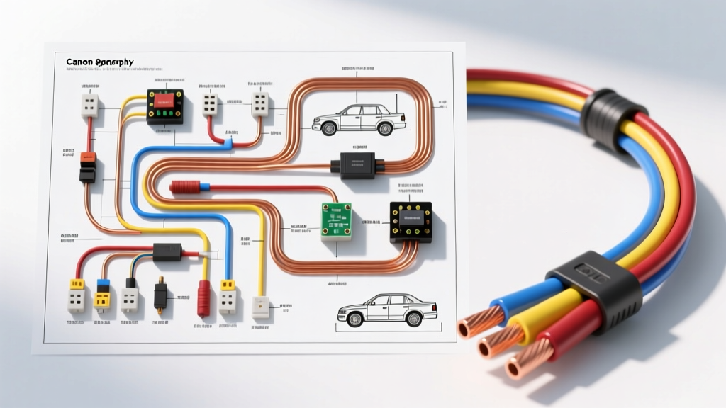
Integrating a Sprinkler System into Work Trucks
Outfitting a landscaping, agricultural, or dust-control work truck with a 12V DC water delivery network requires meticulous electrical planning. Locating an accurate wiring diagram for sprinkler system applications on commercial vehicles can be challenging, as most off-the-shelf diagrams cater to residential 24V AC irrigation controllers. In the automotive realm, we are dealing with 12V DC batteries, high-amperage diaphragm pumps, and harsh environmental exposures. This guide provides a comprehensive cost and tool requirements analysis for building a robust, SAE-compliant truck-mounted sprinkler and dust suppression system.
Cost Analysis: Materials and Electrical Components
Building a reliable 12V DC sprinkler system for a work truck involves balancing upfront material costs against long-term durability. The environment beneath a truck chassis is hostile, characterized by road salt, fertilizer runoff, vibration, and extreme temperature fluctuations. Budgeting for automotive-grade components is non-negotiable to prevent premature voltage drop and parasitic draws.
| Component | Specification | Est. Cost (USD) | Purpose |
|---|---|---|---|
| GXL Primary Wire | 10 AWG & 14 AWG, SAE J1128 | $45.00 | Main pump feed and solenoid branches |
| Bosch Mini ISO Relays | 40A, 5-Pin, Sealed | $14.50 | Isolates high-current pump from cab switch |
| Circuit Breakers | 20A Maxi, Auto-Reset, IP67 | $18.00 | Protects main feed from dead-head stalls |
| Weather-Pack Connectors | 2-Pin & 4-Pin, Delphi/Molex | $28.00 | Waterproof terminations at pump and solenoids |
| Solenoid Valves | 12V DC, 1/2' NPT, Viton Seal | $35.00 ea | Zone control for rear/side spray nozzles |
While a standard hardware store relay might cost $5, it lacks the epoxy-sealed housing required to survive a truck undercarriage. Investing in IP67-rated Bosch-style relays and Delphi Weather-Pack connectors adds roughly $40 to the total project cost but eliminates 90% of moisture-related electrical failures.
Essential Tool Requirements for Automotive Wiring
To execute this wiring diagram for sprinkler system installations properly, standard household electrical tools are insufficient. Automotive wiring demands specific crimping profiles and heat-shrinking techniques to maintain watertight seals. Below is the required tooling checklist:
- Ratcheting Crimper (Molex/Weather-Pack Specific): Standard pliers crush the terminal and compromise the wire barrel. A dedicated ratcheting crimper ensures the terminal wings wrap perfectly around the conductor and insulation.
- Precision Wire Stripper (10-22 AWG): Nicking a single strand of 14 AWG stranded copper reduces its current-carrying capacity and creates a localized hot spot.
- Dual-Temperature Heat Gun: Required for activating marine-grade adhesive-lined heat shrink. The adhesive melts and flows into the wire strands, blocking capillary action from water intrusion.
- Digital Multimeter (True RMS): Essential for measuring voltage drop across the 15-foot run to the rear bumper and testing solenoid coil resistance (typically 8-12 ohms).
- 1/4-Inch Drive Torque Wrench: Grounding lugs must be torqued to chassis specifications (typically 12-15 lb-ft) to prevent vibration-induced loosening.
Wiring Diagram for Sprinkler System: Pinouts and Routing
The core of this truck-mounted sprinkler system relies on a heavy-duty relay to bridge the cab's low-current switch with the high-current demands of the 12V diaphragm pump. Below is the exact pinout configuration for the standard Bosch Mini ISO 5-pin relay used in this schematic.
Bosch Mini ISO Relay Pin Configuration
- Pin 30 (Red 10 AWG): Direct 12V+ feed from the battery positive terminal, routed through a 20A Auto-Reset Maxi Circuit Breaker mounted within 18 inches of the battery.
- Pin 87 (Red 10 AWG): Output to the sprinkler pump positive terminal. This wire carries the full operating load (typically 12-15 Amps).
- Pin 86 (Blue 16 AWG): 12V+ trigger signal from the cab-mounted toggle switch. This switch should be illuminated and fed by an ignition-switched accessory circuit to prevent parasitic battery drain when the truck is parked.
- Pin 85 (Black 16 AWG): Relay coil ground. Terminate this to a clean, bare-metal chassis ground using a ring terminal and a star washer.
- Pin 87a (Not Used): This is the normally closed (NC) terminal. Leave it empty or cap it to prevent accidental shorting.
Solenoid Valve Branch Wiring
If your sprinkler system utilizes multiple zones (e.g., rear dust suppression and side-wash nozzles), you will wire 12V DC solenoid valves in parallel. Use 14 AWG wire for the solenoid feed, protected by a 5A ATO fuse block. The ground wires for the solenoids should be consolidated into a single IP67-rated distribution block mounted near the water tank, rather than relying on individual chassis grounds which are prone to corrosion from fertilizer and road brine.
Voltage Drop Calculations and SAE Standards
Adhering to the SAE J1128 Standard for low-tension primary cable is critical. GXL (General Cross-Linked) wire insulation is preferred over standard PVC because it withstands higher engine bay temperatures and resists abrasion against the truck frame.
Consider a work truck where the water pump is mounted 15 feet from the battery. Using 10 AWG copper wire carrying a 15-Amp load, the voltage drop calculation is as follows:
Voltage Drop = (2 x Length x Current x Resistance per 1000ft) / 1000
Vd = (2 x 15 x 15 x 1.018) / 1000 = 0.45 Volts
A 0.45V drop represents roughly 3.7% of a 12V system. While acceptable for basic lighting, SAE and Bosch Automotive guidelines recommend keeping voltage drop under 3% (0.36V) for inductive loads like DC motors to ensure optimal lifespan and prevent overheating. Upgrading the main feed to 8 AWG wire reduces the voltage drop to 0.28V (2.3%), ensuring the diaphragm pump operates at peak efficiency and maintains consistent water pressure at the sprinkler heads.
Real-World Troubleshooting and Failure Modes
When a truck-mounted sprinkler system fails in the field, the issue is rarely the pump itself. Based on fleet maintenance data, here are the most common electrical failure modes and how to diagnose them using a multimeter:
- Symptom: Pump cycles rapidly on and off.
Cause: Severe voltage drop or a failing ground connection. The pump's internal pressure switch senses a voltage spike when the motor stalls, shutting off prematurely.
Fix: Check the chassis ground for paint or rust. Use a star washer to bite into bare metal and torque to 15 lb-ft. - Symptom: Solenoid clicks but no water flows.
Cause: The solenoid coil is energized, but the internal plunger is stuck due to calcium buildup or debris, or the voltage at the solenoid is below 9V due to undersized wiring.
Fix: Measure voltage directly at the Weather-Pack connector pins while the switch is engaged. If voltage is below 11V, upsize the branch wiring from 16 AWG to 14 AWG. - Symptom: Cab switch melts or becomes hot to the touch.
Cause: The sprinkler pump was wired directly through the dashboard switch without a relay, forcing 15 Amps through a switch rated for 5 Amps.
Fix: Immediately replace the switch and rewire the circuit using the Bosch relay pinout detailed above, ensuring the switch only carries the relay coil current (under 1 Amp).
By investing in the correct automotive-grade tools and adhering to strict SAE wiring standards, your vehicle's sprinkler system will deliver reliable, leak-free operation for thousands of miles of commercial use.