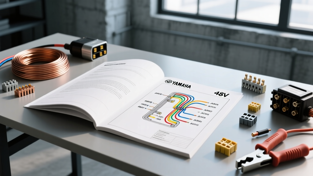
Decoding the Yamaha 48V Golf Cart Wiring Diagram PDF for Project Budgeting
When technicians and fleet managers download a yamaha 48v golf cart wiring diagram pdf, the immediate goal is usually troubleshooting a dead cart or a faulty solenoid. However, from a senior electrical diagnostic perspective, these schematics serve a much more critical secondary function: project scoping and cost analysis. The Yamaha G29 (Drive) 48V DC platform utilizes a complex network of high-current traction circuits and low-voltage logic pathways. Attempting a full chassis rewire or a targeted MCOR (Motor Controller Output Regulator) replacement without first auditing the OEM schematic against your tool inventory and material budget is a recipe for stranded vehicles and voltage drop failures.
This guide breaks down the exact tooling requirements, material costs, and hidden electrical expenses associated with executing a proper 48V Yamaha harness overhaul, using the factory service manual schematics as our baseline.
Essential Tooling for 48V DC High-Current Systems
The yamaha 48v golf cart wiring diagram pdf highlights multiple junction points carrying upwards of 300 amps under peak load (such as hill climbs or heavy payload starts). Standard automotive crimpers and soldering irons are entirely insufficient for the 2 AWG and 2/0 AWG battery cables dictated by the main traction loop. To execute the wiring plan detailed in the PDF, the following specialized tooling is mandatory:
- Hydraulic or Heavy-Duty Ratcheting Crimper (2/0 to 8 AWG): Required for swaging 5/16-inch ring terminals onto main battery cables. A poor crimp here introduces micro-ohms of resistance, leading to thermal runaway at the controller bus bar.
- Digital Multimeter with Min/Max and Peak Hold: Standard multimeters sample too slowly to catch the millisecond voltage spikes generated by the 48V motor during regenerative braking or sudden deceleration. You need a meter capable of capturing transient DC spikes up to 100V to properly test the controller's internal flyback diodes.
- Adhesive-Lined Heat Shrink (3:1 Ratio): The factory diagram specifies sealed environments for all non-cabin connections. Standard PVC electrical tape will degrade under the high ambient heat of a Yamaha G29 battery compartment. 3:1 polyolefin with an inner meltable adhesive layer ensures a watertight seal against battery acid off-gassing.
- Inch-Pound Torque Wrench: Controller terminal nuts (typically 5/16-18 UNF) must be torqued to exactly 110 in-lbs. Under-torquing causes arcing; over-torquing strips the soft copper bus bars inside the Yamaha/Curtis controller.
Material Cost Breakdown: Rewiring the G29 (Drive) Chassis
By cross-referencing the OEM yamaha 48v golf cart wiring diagram pdf with current market prices for high-strand-count, pure-copper SAE J1128 compliant wire, we can build an accurate budget for a complete main harness replacement. Avoid Copper Clad Aluminum (CCA) wire at all costs; the schematic's voltage drop calculations assume 100% annealed copper.
| Component / Wire Type | AWG / Spec | OEM Color Code | Est. Cost (USD) | Function per Schematic |
|---|---|---|---|---|
| Main Battery to Controller B+ | 2 AWG (Flex) | Red | $38.00 (8 ft) | Primary high-current traction feed |
| Main Battery to Controller B- | 2 AWG (Flex) | Black | $38.00 (8 ft) | Primary high-current ground return |
| Solenoid to Motor Field/Armature | 4 AWG (Flex) | Red / Yellow | $45.00 (10 ft) | Switched high-current motor drive |
| Key Switch & F/R Switch Harness | 16 AWG (TXL) | White / Green | $18.00 (15 ft) | Low-current logic and coil activation |
| 300A Class T Fuse & Block | Class T | N/A | $42.00 | Main short-circuit protection (B+ line) |
| 48V Heavy Duty Solenoid (OEM) | Continuous Duty | N/A | $85.00 | High-amperage circuit switching |
| MCOR Throttle Assembly | Hall Effect | N/A | $145.00 | Throttle position signaling to ECU |
| Pre-Charge Resistor (300 Ohm) | 10W Wirewound | N/A | $12.00 | Prevents contact arcing at solenoid |
Total Estimated Material Cost for Main Harness & Core Components: $423.00
Main Power Harness vs. Low-Voltage Accessory Circuits
The PDF schematic clearly delineates the 48V traction system from the 12V accessory system (lights, horn, USB chargers). A common and costly mistake is tapping into the 48V pack for 12V accessories using a cheap resistor-based voltage reducer. The wiring diagram dictates the use of an isolated DC-DC step-down converter (48V to 12V, minimum 15A). Budget an additional $65.00 for a quality isolated converter to prevent frying low-voltage logic boards and LED headlights when the main motor generates regenerative voltage spikes.
Tracing the MCOR and Solenoid Circuits: Hidden Diagnostic Costs
The most frequently misdiagnosed section of the Yamaha 48V schematic is the interaction between the Key Switch, the Forward/Reverse (F/R) microswitches, and the MCOR. If your cart 'clicks' but doesn't move, the PDF directs you to check the solenoid activation circuit.
The Pre-Charge Resistor Failure Mode
According to the factory diagram, a 300-ohm, 10-watt pre-charge resistor is wired in parallel across the main solenoid's high-current terminals. Its job is to allow a small amount of current to flow into the controller's main capacitors before the heavy solenoid contacts close. If this $12 resistor burns out (a very common failure mode), the solenoid is forced to equalize the voltage across dead capacitors, resulting in massive arcing that welds the solenoid contacts shut or melts the 5/16-inch ring terminals. Replacing the solenoid without checking the pre-charge circuit on the schematic will result in a destroyed $85 replacement solenoid within a week.
MCOR Pinout and Calibration
Unlike older V-Glide potentiometers, the G29 MCOR is a non-contact Hall effect sensor. The wiring diagram specifies a 4-pin connector:
- Pin 1 (Red): 5V Reference from Controller
- Pin 2 (Blue): Throttle Signal Output (0.8V at rest, 3.4V at full throttle)
- Pin 3 (Black): Sensor Ground
- Pin 4 (White): Footbrake Microswitch Interlock
If the PDF indicates 5V at Pin 1 but the Blue signal wire outputs 1.2V at rest (instead of the specified 0.8V), the controller's safety logic will inhibit the solenoid from engaging. This requires physical recalibration of the MCOR mounting bracket, not a harness replacement. Misunderstanding this pinout leads to unnecessary $145 part replacements.
Hidden Costs: Voltage Drop and Terminal Degradation
When budgeting a wiring project based on the yamaha 48v golf cart wiring diagram pdf, you must account for terminal degradation. Yamaha's OEM harness uses specific tin-plated copper lugs to resist galvanic corrosion caused by the sulfuric acid off-gassing from the flooded lead-acid battery bank. If you are upgrading to aftermarket lithium (LiFePO4) batteries, the BMS (Battery Management System) requires pristine, low-resistance connections to accurately read cell voltages.
Budget an extra $40 for a high-quality wire brushing tool and dielectric grease. Applying dielectric grease over the exterior of the torqued terminal (never between the mating metal surfaces) prevents the ingress of moisture and battery acid, preserving the integrity of the circuit as outlined in the OEM maintenance schedules.
Sourcing and Verifying OEM PDF Schematics
Not all wiring diagrams found online are accurate. Many third-party forums host modified schematics that reflect aftermarket lift kits or unauthorized motor upgrades. For baseline cost and tool analysis, always refer to the official Yamaha Golf Car Service Manual for your specific chassis year. The SAE J1128 standard provides the definitive guidelines for low-tension primary cable specifications, ensuring the wire you purchase matches the ampacity requirements detailed in the Yamaha schematic. Furthermore, referencing Littelfuse Class T technical data is crucial when selecting the main B+ fuse, as standard ANL fuses lack the rapid interrupt rating required to safely protect a 48V DC controller from catastrophic short-circuit events.
By treating the yamaha 48v golf cart wiring diagram pdf not just as a map, but as a comprehensive bill of materials and diagnostic flowchart, you eliminate guesswork, prevent secondary electrical failures, and ensure your G29 operates at peak electrical efficiency.