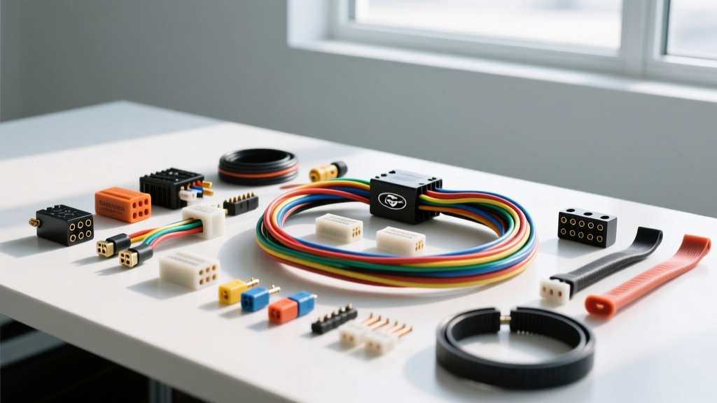
Why the Factory 1966 Mustang Wiring Harness Fails
The 1966 Ford Mustang is an undisputed automotive icon, but its original electrical system was designed for a different era. Factory harnesses from the mid-1960s utilized PVC insulation that, over five decades, suffers from plasticizer migration. This off-gassing process leaves the wire insulation brittle, cracked, and highly susceptible to shorting against the steel unibody. Furthermore, the 1966 model year was a transitional period for Ford; while many models still relied on the outdated Autolite generator, the electrical demands of modern RestoMod builds—featuring electric cooling fans, fuel injection, and high-output audio systems—far exceed the capacity of the original 40-amp generator and 14-gauge factory wiring.
When undertaking a comprehensive upgrade and modification project, replacing the brittle factory copper with a modern, cross-linked polyethylene (XLPE) insulated harness is not just a cosmetic improvement; it is a critical fire-prevention measure. According to SAE J1128 standards, modern XLPE wire offers superior resistance to under-hood temperatures, maintaining dielectric integrity at up to 125°C, compared to the 90°C limit of vintage PVC.
The Danger of the Factory Ammeter Loop
One of the most hazardous design flaws in the 1966 Mustang wiring harness is the factory ammeter routing. In the original configuration, the entire output of the charging system travels from the alternator or generator, through the firewall, into the dash ammeter gauge, and then back out to the main splice block. This means full charging current—often 40 to 60 amps in a modified setup—is routed through 10 AWG copper wires directly behind a steel dash panel. If the brittle insulation cracks and the positive ammeter wire contacts the grounded dash frame, it creates a dead short that can melt the harness and ignite a dashboard fire before the main fusible link has time to blow.
Modern aftermarket harness kits address this by converting the ammeter to a high-impedance voltmeter. A voltmeter only draws milliamps, allowing the heavy charging current to be routed directly from the alternator to the starter solenoid battery post via a dedicated 4 AWG or 6 AWG cable, completely bypassing the passenger compartment.
Selecting the Right 1966 Mustang Wiring Harness Kit
When selecting a harness kit, builders must choose between an OEM-style reproduction harness and a universal RestoMod chassis harness. Reproduction harnesses maintain the exact factory wire colors, bulkhead connectors, and fuse block locations. While excellent for concours restorations, they lack the auxiliary circuits required for modern upgrades.
For modification projects, a 21-circuit or 28-circuit universal chassis harness (such as those from Painless Performance or American Autowire) is vastly superior. These kits feature a centralized, blade-style ATO/ATC fuse block, dedicated relays for high-draw components like headlamps and electric fans, and pre-terminated bulkhead connectors that seal the firewall pass-through. According to installation guidelines from Painless Performance, mounting the modern fuse block on the driver-side kick panel or under the dash utilizing a dedicated ground bus bar drastically simplifies troubleshooting and future circuit expansion.
Critical AWG and Circuit Specifications
Proper wire gauge selection is dictated by the amperage draw and the length of the circuit. Voltage drop over distance necessitates stepping up the AWG size for runs exceeding 10 feet. Below is the recommended specification chart for a modernized 1966 Mustang RestoMod build:
| Circuit Function | Wire Color (Typical) | AWG Size | Fuse Rating | Notes |
|---|---|---|---|---|
| Alternator Output | Heavy Red / Black | 4 AWG | 120A Mega | Direct to starter solenoid |
| Headlamps (Relay Fed) | Red w/ Black Hash | 12 AWG | 20A | Use 30A relays at lamps |
| Ignition Coil (Points) | Pink (Resistance) | 14 AWG | 10A | 1.5 ohm resistor wire |
| Ignition Coil (HEI/EFI) | White / Yellow | 12 AWG | 15A | Full 12V, non-resistance |
| Electric Cooling Fan | Dark Blue | 10 AWG | 30A | Must use 40A relay |
| Tail / Parking Lamps | Brown | 14 AWG | 10A | Check for bad grounds |
| EFI / ECU Main Power | Red | 10 AWG | 20A | Relay triggered by ignition |
Alternator Conversion and Ammeter Bypass
The 1966 Mustang originally came equipped with a generator, which is inadequate for modern electrical loads. Upgrading to a 1-wire GM 10SI or a Ford 3G internally regulated alternator is standard practice. As detailed by the charging system experts at M.A.D. Enterprises, the 1-wire alternator requires only a single heavy-gauge output wire connected directly to the battery side of the starter solenoid.
When performing this swap, the original generator voltage regulator mounted on the driver-side inner fender must be removed or bypassed. The original 10 AWG black/yellow charge wire that ran through the ammeter must be abandoned. Instead, run a new 4 AWG stranded copper wire from the alternator output stud, through a 120-amp Mega fuse, directly to the battery terminal on the starter solenoid. This ensures minimal voltage drop and completely eliminates the fire hazard associated with the dash ammeter loop.
Bulkhead Pass-Through and Firewall Routing
The 1966 Mustang utilizes a specific driver-side firewall bulkhead connector that differs slightly from the 1965 and 1967 models, particularly regarding the routing of the turn signal and backup light circuits. When installing an aftermarket harness, you will typically drill a new pass-through hole or utilize the factory heater core delete plate to route the engine bay sub-harness.
Always use a high-quality, ribbed rubber firewall grommet to protect the wire loom from the sharp sheet metal edges of the unibody. Before pulling the harness through the grommet, coat the wires generously with a dielectric grease such as Nyogel 760G. This not only reduces friction during installation but also creates a moisture barrier that prevents capillary action from drawing water into the passenger compartment. Secure the harness on the engine bay side using adhesive-lined heat shrink clamps, maintaining at least 2 inches of clearance from the exhaust manifolds and moving steering column linkage.
Unibody Grounding Strategy
The 1966 Mustang's unibody construction relies heavily on sheet metal screws and spot welds for electrical ground returns. Over time, rust, seam sealer, and fresh paint disrupt these paths, leading to dim headlights, erratic gauge behavior, and fuel pump starvation. A modern harness upgrade must be paired with a dedicated star-grounding system.
Install a brass or copper ground bus bar on the inner fender or firewall. Run a dedicated 8 AWG ground strap from the engine block to the chassis, a 10 AWG strap from the cylinder head to the firewall, and a 10 AWG strap from the transmission bellhousing to the unibody frame rail. When attaching ground lugs to the sheet metal, drill out the paint and seam sealer down to bare, shiny steel. Use a star washer between the ring terminal and the metal, and torque the self-tapping grounding screws or bolted rivet nuts to 15 ft-lbs to ensure a permanent, low-resistance connection.
Terminal Crimping and Connector Standards
The longevity of your 1966 Mustang wiring harness upgrade depends heavily on termination quality. Soldering is generally discouraged in high-vibration automotive environments because solder wicks into the wire strands, creating a rigid point that is prone to work-hardening and snapping. Instead, use open-barrel stamping terminals, such as the Packard 56-series used extensively in Ford applications.
Invest in a professional-grade open-barrel crimping tool (such as those from TE Connectivity or Delphi). A proper crimp creates a cold-weld between the copper strands and the terminal brass, ensuring a gas-tight seal that prevents oxidation. For connections exposed to the elements, such as the headlamp buckets, horn relay, and voltage regulator plugs, upgrade to sealed Weather-Pack or Deutsch DT connectors. These utilize silicone seals that block moisture ingress and feature secondary locking tabs that prevent terminal back-out under vibration.
Troubleshooting Post-Install Voltage Drop
After installing the new harness, perform a comprehensive voltage drop test before sealing up the dash panels. Set your digital multimeter to DC Volts. With the engine running and the electrical load applied (headlights and heater blower on high), place the red probe on the alternator output post and the black probe on the battery positive post. A reading higher than 0.2V indicates excessive resistance in the positive charge cable, requiring an upsized AWG wire or cleaning of the terminal crimps.
Similarly, test the ground side by placing the red probe on the battery negative post and the black probe on the engine block. Any reading above 0.1V signifies a poor engine-to-chassis ground strap. By adhering to these strict AWG specifications, routing protocols, and termination standards, your 1966 Mustang will feature an electrical system capable of supporting modern performance upgrades while remaining entirely reliable and safe for decades to come.