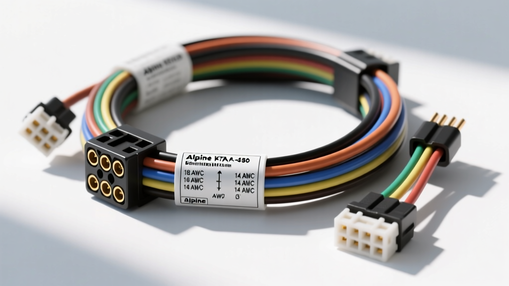
Introduction to the Alpine KTA-450 Harness Architecture
The Alpine KTA-450 is a highly efficient, compact 4-channel amplifier designed for seamless OEM integration and aftermarket upgrades. Because of its small footprint, the Alpine KTA-450 wiring harness is often routed through tight firewall grommets, under dashboards, or integrated directly into factory T-harnesses behind the head unit. While the amplifier itself is remarkably reliable, harness-related failures—ranging from voltage drops on the power circuit to high-level input signal shorts—are the leading cause of installation headaches.
This comprehensive troubleshooting guide provides a systematic, step-by-step decision tree to isolate and resolve wiring harness faults. Whether you are dealing with a custom-fabricated harness, an Alpine KTE-450 integration T-harness, or a direct-splice OEM adapter, this flow will help you identify the root cause using standard automotive electrical diagnostic procedures.
Pre-Troubleshooting Safety & Tool Requirements
Before probing the Alpine KTA-450 wiring harness, ensure you have the correct diagnostic equipment. Guessing with a test light can damage the amplifier's internal logic board or SMD components.
- Digital Multimeter (DMM): Required for measuring DC voltage, voltage drop, and continuity. Must have a high-impedance input.
- Tone Generator and Inductive Probe: Essential for tracing speaker wires through OEM T-harnesses without piercing insulation.
- Wire Stripper/Crimper: For repairing damaged 10 AWG to 18 AWG terminals.
- Dielectric Grease: For sealing repaired connections against galvanic corrosion.
Safety Note: Always disconnect the vehicle's negative battery terminal before cutting, splicing, or re-crimping any wires on the main power or ground circuits to prevent accidental short circuits.
Alpine KTA-450 Wiring Harness Pinout & Specifications
Understanding the baseline specifications of the harness is critical. The KTA-450 utilizes a 15A ATO blade fuse on the main power line, meaning the wiring must adhere to strict SAE J1128 standards for low-tension primary cable to prevent voltage drop and thermal runaway. Below is the standard pinout and wire gauge requirement for the KTA-450 power and speaker harness.
| Wire Function | AWG Size | EIA / MECA Color Code | Terminal / Pin Type |
|---|---|---|---|
| +12V Constant Power | 10 - 12 AWG | Red | Spade Connector / Ring Terminal |
| Chassis Ground | 10 - 12 AWG | Black | Ring Terminal (Bare Metal) |
| Remote Turn-On | 18 AWG | Blue w/ White Stripe | Butt Splice / Quick Splice |
| Front Left (+ / -) | 16 - 18 AWG | White / White w/ Black | T-Harness Plug / Solder Seal |
| Front Right (+ / -) | 16 - 18 AWG | Gray / Gray w/ Black | T-Harness Plug / Solder Seal |
| Rear Left (+ / -) | 16 - 18 AWG | Green / Green w/ Black | T-Harness Plug / Solder Seal |
| Rear Right (+ / -) | 16 - 18 AWG | Purple / Purple w/ Black | T-Harness Plug / Solder Seal |
Step-by-Step Troubleshooting Decision Tree
Follow this symptom-cause-fix decision tree to isolate faults within the Alpine KTA-450 wiring harness.
Symptom 1: Amplifier Will Not Power On (No LED Illumination)
Initial Observation: The KTA-450 power LED remains completely dark when the ignition is turned to the ACC or ON position.
- Cause A: Blown Main Fuse or Power Wire Break.
- Fix: Check the 15A ATO fuse within 18 inches of the battery. If intact, use a DMM to measure DC voltage between the Red (+12V) spade terminal at the amplifier and a known good chassis ground. You must read between 12.2V and 14.4V. If 0V, trace the red wire back to the firewall for pinched insulation or a loose ring terminal at the battery.
- Cause B: High Resistance Ground.
- Fix: Measure voltage between the Black (Ground) terminal on the amp harness and the negative battery post. If you read battery voltage (12V+) with the amp disconnected, your ground point is floating. Scrape away paint, primer, and rust to bare metal, and secure with an M6 or M8 bolt torqued to factory chassis specs.
- Cause C: Remote Turn-On (REM) Circuit Failure.
- Fix: Probe the Blue/White 18 AWG wire at the harness connection. It requires a minimum of 9V DC to trigger the internal relay. If using an OEM integration T-harness, ensure the remote wire is tied to an ignition-switched 12V+ source or a data module's remote output, not a dimmer or illumination circuit.
Symptom 2: Amplifier Powers On But Yields No Audio Output
Initial Observation: The LED is blue (or white), indicating the amp is on, but the speakers produce no sound.
- Cause A: Incorrect Input Mode Selection.
- Fix: The KTA-450 features a physical switch on the chassis for 'RCA' vs 'Speaker Level' inputs. If you are using the wiring harness to tap into factory speaker wires (High-Level Input), ensure the switch is set to Speaker Level. If using RCA cables, it must be set to RCA.
- Cause B: T-Harness Pinout Mismatch.
- Fix: Aftermarket T-harnesses (like Metra or Axxess) vary by vehicle make. Use an inductive tone probe to verify that the White/Gray/Green/Purple wires on the amp harness perfectly match the corresponding OEM speaker wires at the radio plug. A swapped Front/Rear or Left/Right pinout will cause phase cancellation or silence if the OEM head unit features active crossovers.
- Cause C: Blown Internal Speaker Output Fuses.
- Fix: If a speaker wire was shorted to ground during installation, the KTA-450's internal protection may have tripped or blown an internal SMD fuse. Disconnect all speaker harnesses, reset the amp by removing the main 15A fuse for 60 seconds, and reconnect power.
Symptom 3: Amplifier Enters Protect Mode (Red LED)
Initial Observation: The amplifier turns on briefly, then the LED shifts to red, muting all audio outputs.
- Cause A: Speaker Wire Short Circuit.
- Fix: This is the most common harness fault. A stray strand of 16 AWG copper from the White (FL+) wire may be touching the White/Black (FL-) wire or the chassis ground. Disconnect the entire speaker harness from the amplifier. Power the amp on. If the LED stays blue, the short is definitively in the vehicle-side speaker wiring. Inspect all door hinge boots and kick panel areas for pinched wires.
- Cause B: Impedance Mismatch / Overheating.
- Fix: The KTA-450 is stable down to 2 ohms per channel. If the harness is wired to bridge channels incorrectly or parallel multiple speakers, the impedance drops below 2 ohms, triggering thermal or current protection. Verify speaker voice coil wiring at the door panels.
Symptom 4: Alternator Whine or Ground Loop Noise
Initial Observation: A high-pitched whine that increases in pitch with engine RPM is audible through the speakers.
- Cause A: Ground Loop via T-Harness.
- Fix: When using high-level inputs via an OEM T-harness, the head unit's ground and the amplifier's ground must share the same reference point. If the amp is grounded to the rear chassis and the radio is grounded to the dash, a ground loop occurs. Run a dedicated 10 AWG ground wire from the amplifier's ground terminal directly to the head unit's chassis ground point to equalize the reference voltage.
- Cause B: Power and Signal Wire Induction.
- Fix: Ensure the 10 AWG Red power wire and the 16 AWG speaker harness wires are routed down opposite sides of the vehicle. Running high-current power wires parallel to low-level audio signals induces electromagnetic interference (EMI).
Advanced Multimeter Testing Procedures
For intermittent issues where the Alpine KTA-450 wiring harness fails only when the vehicle is in motion or when the bass hits hard, perform a Voltage Drop Test.
- Set your DMM to DC Volts (20V scale).
- Turn the radio on and play a test tone (50Hz) at moderate volume to place a load on the amplifier.
- Place the Red probe directly on the amplifier's +12V terminal and the Black probe on the positive post of the vehicle battery. A reading higher than 0.5V indicates excessive resistance in the power wire (undersized AWG or corroded firewall pass-through).
- Place the Red probe on the negative battery post and the Black probe on the amplifier's Ground terminal. A reading higher than 0.1V indicates a poor chassis ground connection. According to Mobile Electronics Association (MEA) standards, any ground circuit voltage drop exceeding 0.1V under load will severely compromise Class-D amplifier efficiency and introduce clipping.