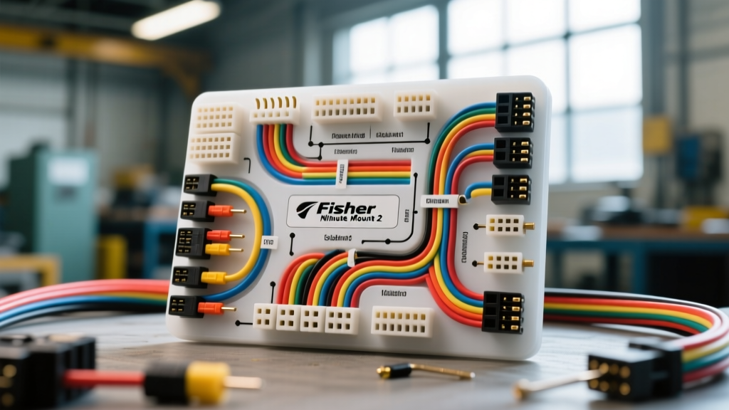
Introduction to the Fisher MM2 Electrical System
The Fisher Minute Mount II (MM2) is an industry-standard snow plow mounting system, but its electrical architecture is where many installers make critical errors. Unlike older direct-wire setups, the modern Fisher MM2 wiring harness utilizes an isolation module and a 13-pin multiplex-style connector to separate the plow's lighting and control circuits from the truck's OEM CAN-bus or multiplexed headlight systems. This prevents hyper-flashing, bulb-out warnings, and PCM (Powertrain Control Module) faults on modern trucks.
This comprehensive guide details the exact installation procedure for the truck-side and plow-side harnesses, including heavy-gauge power routing, isolation module integration, and 13-pin connector pinout mapping. Whether you are wiring a 2018 Ford F-250 or a 2022 Ram 2500, adhering to SAE standards and proper crimping techniques is non-negotiable for reliable winter operation.
Pre-Installation Preparation & Tool List
Before cutting a single zip tie, disconnect the negative battery terminal to prevent shorting the truck's BCM (Body Control Module) during headlamp harness splicing. Gather the following professional-grade tools:
- Wire Strippers & Crimpers: Ratcheting crimpers capable of handling 16 AWG to 6 AWG terminals.
- Heat Shrink & Solder Seal Connectors: Avoid standard vinyl electrical tape; use dual-wall adhesive-lined heat shrink for all under-hood splices.
- Dielectric Grease: Nyogel 760G or equivalent lithium-based dielectric grease for the 13-pin connector.
- Multimeter: For verifying 12V reference signals and continuity testing.
- Firewall Grommet & Fish Tape: For safe cab routing of the control harness.
For wire specifications, always refer to SAE J1128 standards for low-tension primary cables, ensuring you use stranded copper wire rated for under-hood temperature extremes.
Step-by-Step Truck-Side Harness Routing
Step 1: Power and Ground Cable Routing
The MM2 hydraulic pump requires massive instantaneous current draw, often exceeding 150 amps during startup. The kit includes heavy-duty power and ground cables.
- Power Cable (Red, 6 AWG): Route the red power cable from the plow grill area to the truck's positive battery terminal. Critical: You must install the provided 150A circuit breaker or Mega fuse within 18 inches of the battery positive post. This complies with ABYC and SAE safety standards to protect the harness in the event of a dead short.
- Ground Cable (Black, 6 AWG): Route the black cable from the grill to the engine block or negative battery terminal. If grounding to the engine block, use a wire brush to remove paint and corrosion, ensuring bare metal-to-metal contact. Coat the terminal with anti-corrosion spray after torquing to 15 ft-lbs.
Step 2: Isolation Module & Headlamp Harness Integration
The isolation module acts as a relay bridge, reading the truck's headlight signals and switching power to the 13-pin connector without drawing excessive current through the truck's OEM BCM.
- Locate the truck's OEM headlamp connectors. Plug the Fisher vehicle-specific headlamp harness inline between the truck's factory plug and the truck's headlight bulb.
- Route the harness along the factory wiring loom, securing it every 12 inches with UV-resistant zip ties. Keep the harness at least 6 inches away from exhaust manifolds and turbocharger piping.
- Mount the isolation module in a protected area behind the grille or bumper, ensuring the connector faces downward to prevent water pooling.
Step 3: Cab Control Harness Routing
The control cable must pass from the engine bay into the cab to connect to the joystick or touchpad controller.
- Locate an existing firewall grommet (often near the brake booster or main body harness). If none is available, drill a 3/4-inch hole in a flat section of the firewall.
- Insert a rubber firewall grommet to protect the harness from sharp sheet metal edges.
- Use a fish tape to pull the control harness into the cab. Ensure there is a 'drip loop' on the engine side so water cannot track down the wire and into the cab.
Fisher MM2 13-Pin Connector Pinout Reference
The 13-pin connector is the nerve center of the MM2 lighting and control system. Below is the standard pinout configuration. Note that wire colors may vary slightly depending on the specific vehicle adapter kit, but the pin functions remain standardized across the MM2 platform.
| Pin | Function | Typical Wire Color | AWG Size |
|---|---|---|---|
| 1 | Left Turn / Stop | Yellow | 16 AWG |
| 2 | Right Turn / Stop | Green | 16 AWG |
| 3 | System Ground | Black | 12 AWG |
| 4 | Tail / Marker Lights | Brown | 16 AWG |
| 5 | Left Headlamp (High Beam) | Blue | 14 AWG |
| 6 | Right Headlamp (High Beam) | White/Blue | 14 AWG |
| 7 | Left Headlamp (Low Beam) | Red | 14 AWG |
| 8 | Right Headlamp (Low Beam) | White/Red | 14 AWG |
| 9 | Auxiliary / Backup | Purple | 16 AWG |
| 10 | 12V Switched Ignition Power | Red | 12 AWG |
| 11 | Control / Data (to Joystick) | Orange | 18 AWG |
| 12 | Spare | - | - |
| 13 | Spare | - | - |
Reference: For comprehensive wire gauge current-carrying capacities, consult the Del City Wire Gauge Chart to ensure voltage drop is minimized over the length of the harness.
Step-by-Step Plow-Side Harness Connection
The plow-side harness is subjected to extreme vibration, salt, and moisture. Proper assembly here dictates the lifespan of your equipment.
- Mount the Receptacle: Secure the plow-side 13-pin receptacle to the A-frame or headgear assembly using stainless steel hardware. Apply anti-seize compound to the threads to prevent galvanic corrosion.
- Route the Harness: Run the harness down the A-frame, securing it to the hydraulic hoses. Leave enough slack at the pivot points so the harness does not stretch when the plow is angled fully left or right.
- Connect to Plow Lights: Plug the sealed connectors into the plow's headlamps and marker lights. Ensure the locking tabs click firmly into place.
- Apply Dielectric Grease: Coat the male pins of the truck-side plug and the female sockets of the plow-side receptacle with a generous amount of dielectric grease. This displaces moisture and prevents the formation of copper oxide, which causes voltage drops and flickering lights.
Testing and Real-World Troubleshooting
After reconnecting the truck battery, turn the ignition to the 'ON' position and engage the plow controller. Use the following decision tree to diagnose common installation faults:
- Symptom: Truck lights turn off, but plow lights do not turn on.
Cause: Isolation module is not detecting the truck's headlight signal, or Pin 3 (Ground) on the 13-pin connector is compromised.
Fix: Use a multimeter to verify the truck-side headlamp adapter is sending 12V to the module trigger wire. Check Pin 3 continuity to the chassis ground. - Symptom: Plow lights flicker rapidly when the engine is running.
Cause: Alternator ripple voltage or a loose 6 AWG ground cable causing a floating ground.
Fix: Re-torque the 6 AWG ground cable to the engine block. Verify the isolation module ground wire is attached to a clean, unpainted metal surface. - Symptom: Controller displays 'No Plow Detected' or flashes red.
Cause: Pin 10 (Switched Power) or Pin 11 (Control/Data) is severed or lacking 12V reference.
Fix: Trace the red wire on the truck-side harness to the ignition-switched fuse box tap. Ensure the add-a-circuit fuse is properly seated and rated for 10A. - Symptom: Hydraulic pump solenoid clicks, but motor does not run.
Cause: Voltage drop across the 150A breaker or corroded motor ground strap.
Fix: Perform a voltage drop test across the breaker while under load. If the drop exceeds 0.5V, replace the breaker or clean the terminal connections.
Expert Maintenance Tips for Corrosion Prevention
The number one killer of snow plow wiring harnesses is galvanic corrosion inside the 13-pin connector. At the end of every plowing season, disconnect the harness, wash both halves with electrical contact cleaner, and inspect the pins for green verdigris. If pins are pitted, use a fiberglass scratch pen to clean them, or replace the connector head using a weather-pack crimp tool. Always store the disconnected truck-side plug in a sealed PVC cap or specialized weather boot to prevent road salt from accumulating in the cavities during the summer months. For more detailed OEM schematics and module flashing procedures, refer to the Fisher Engineering Official Tech Library.