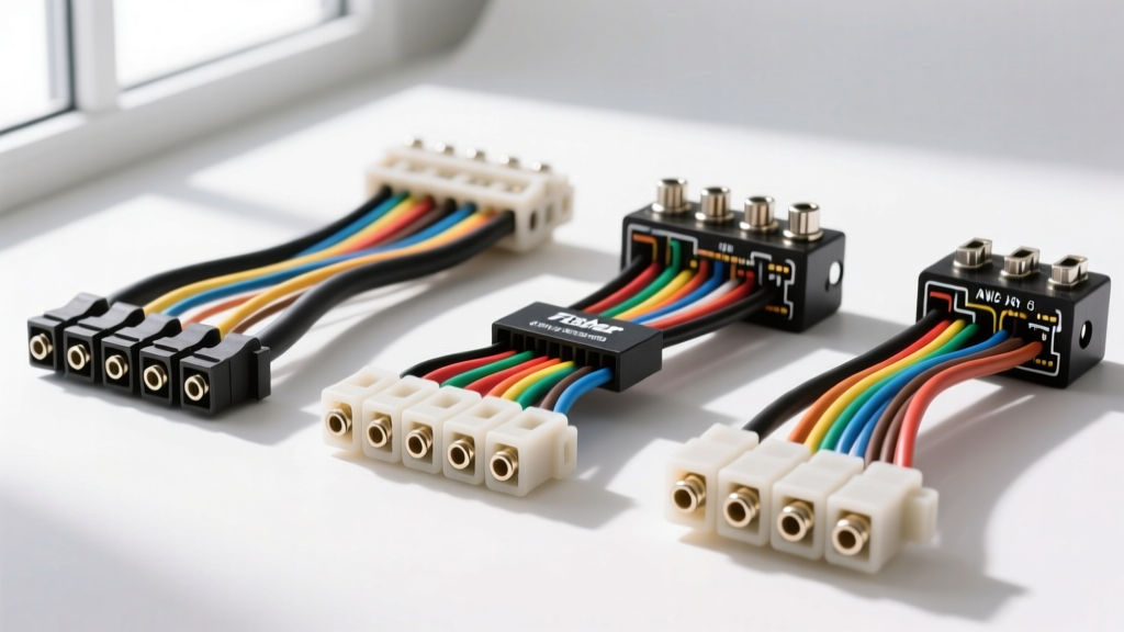
Understanding the Fisher Poly Caster Wiring Ecosystem
When equipping a truck with a Fisher Engineering Poly plow—such as the MVP3, HD, or SD series—the electrical system is the lifeline of the entire operation. The Fisher Poly caster wiring harness and main control harnesses are responsible for transmitting high-amperage power to the electric-hydraulic power unit (EHPU) while simultaneously routing low-voltage signals for the lighting, blade articulation, and mechanical caster stops. Because snow plowing subjects electrical components to extreme moisture, road salt, and severe vibration, selecting the correct harness kit is not just a matter of convenience; it is a matter of operational safety and reliability.
At AutoFlowWire, we frequently see plow operators struggle with intermittent blade movements or total EHPU failures due to undersized aftermarket wiring or degraded OEM connectors. This comprehensive selection guide compares OEM Fisher harness kits with high-quality aftermarket alternatives, breaks down the exact AWG requirements, and provides a master pinout reference to ensure your plow operates flawlessly in the harshest winter conditions.
OEM vs. Aftermarket: Which Harness Kit Should You Choose?
The market for Fisher plow wiring is divided between genuine Fisher Engineering OEM replacements and third-party aftermarket kits (such as those from Buyers Products or Curt). Understanding the engineering differences is critical when selecting a Fisher Poly caster wiring harness or main vehicle-side adapter.
1. Genuine Fisher OEM Harness Kits
OEM Fisher harnesses (e.g., Part #26345 for MM2 systems or #28048 for 13-pin MVP3 setups) are engineered specifically for the inductive loads of Fisher solenoids and motors. They feature proprietary molded strain reliefs at the connector boots, which are the most common failure points in plow wiring. The wire jacketing meets strict SAE J1128 Low Tension Primary Cable standards, ensuring resistance to abrasion, battery acid, and extreme cold-cracking down to -40°F. The copper stranding is typically high-count (e.g., 105 strands for 10 AWG), providing superior flexibility for the constant A-frame articulation.
2. Premium Aftermarket Equivalents
High-end aftermarket kits can offer cost savings of 20% to 30% while maintaining reliable performance, provided they use marine-grade tinned copper and sealed Metri-Pack or Weather-Pack terminals. However, budget aftermarket kits often use rigid, low-strand-count copper-clad aluminum (CCA) wire. CCA wire suffers from higher resistance, leading to severe voltage drop at the EHPU motor during high-load angling operations, which can prematurely burn out the motor armature or trigger the thermal breaker.
Technical Specifications: Wire Gauge and Amperage Requirements
Whether you are repairing a damaged section of your existing harness or building a custom adapter for a fleet truck, adhering to the correct American Wire Gauge (AWG) specifications is non-negotiable. The Fisher EHPU motor can draw upwards of 150 amps under stall conditions (e.g., when the blade is hard-packed against a snowbank).
| Circuit / Component | Standard Wire Color | Minimum AWG Size | Max Amperage | Connector / Terminal Type |
|---|---|---|---|---|
| Battery to Solenoid (Power) | Red | 2 AWG | 150A - 200A | 3/8" Ring Terminal (Heat Shrink) |
| Solenoid to EHPU Motor | Black / Red | 2 AWG | 150A - 200A | Motor Stud Ring Terminal |
| Solenoid Trigger (Control) | White / Red | 10 AWG | 20A | 13-Pin Molded / 1/4" Spade |
| Lighting & Valve Controls | Multi-color | 14 AWG to 12 AWG | 10A - 15A | 13-Pin Sealed Molded Plug |
| Main System Ground | Black | 2 AWG | 150A+ | 3/8" Ring to Clean Chassis |
13-Pin Connector Pinout Configuration (MVP3 / Poly HD)
Newer Fisher Poly plows utilize a 13-pin sealed connector system to manage the complex electro-hydraulic valving and LED lighting arrays. When diagnosing a Fisher Poly caster wiring harness issue, use a digital multimeter to back-probe these pins at the vehicle-side grill connector. Always refer to the official Fisher Engineering Service Manuals for your specific serial number, but the standard 13-pin logic generally follows this architecture:
- Pin 1 (Black): Ground (Lighting & Control Common)
- Pin 2 (Brown): Park / Marker Lights
- Pin 3 (Green): Right Turn / Stop
- Pin 4 (Yellow): Left Turn / Stop
- Pin 5 (White): Ground (Motor Return Path / Secondary)
- Pin 6 (Blue): High Beam Headlights
- Pin 7 (Red): Solenoid Trigger (Power from Cab Control)
- Pin 8 (Orange): Valve Coil Common (Angling / Lift)
- Pin 9 (Purple): Valve Coil A (e.g., Lift Up)
- Pin 10 (Light Blue): Valve Coil B (e.g., Angle Left)
- Pin 11 (Dark Blue): Valve Coil C (e.g., Angle Right)
- Pin 12 (Pink): Auxiliary / Caster Stop Mechanism Signal
- Pin 13 (Red/White): 12V Battery Feed for Cab Control Memory
Common Failure Modes and Diagnostic Troubleshooting
When a Fisher Poly plow fails to respond to cab commands, the issue is rarely the hydraulic pump itself; it is almost always a failure within the wiring harness or the main power solenoid. Here is a diagnostic decision tree based on real-world fleet maintenance data.
Symptom: Solenoid Clicks, But Motor Does Not Run
Cause: High resistance in the 2 AWG power cables or a failing Trombetta/White-Rodgers solenoid. The control circuit has enough amperage to pull the solenoid plunger (creating the 'click'), but the corroded main contacts inside the solenoid cannot pass the 150A required by the motor.
Fix: Perform a voltage drop test across the solenoid's large B (Battery) and M (Motor) terminals while a helper holds the 'Lift' button. A voltage drop greater than 0.5V indicates internal solenoid corrosion. Replace the solenoid and apply anti-oxidant paste to the 2 AWG ring terminals.
Symptom: Plow Angles Slowly or Stutters
Cause: Voltage drop in the 10 AWG to 14 AWG control harness pins (Pins 8-11). Road salt intrusion into the 13-pin connector causes micro-corrosion, increasing resistance. The hydraulic valve coils require a solid 12V to open fully; if they only receive 9V due to harness resistance, the valve chatters.
Fix: Disconnect the 13-pin connector. Inspect the female cavities for green copper oxide. Clean with electrical contact cleaner and a nylon brush. Pack the connector boots with Nyogel 760G or a high-quality dielectric grease to displace moisture. If pins are heavily pitted, use a Delphi extraction tool to remove them and crimp new sealed terminals using a proper ratcheting crimper.
Symptom: Blown Thermal Breaker or Melted Harness Jacket
Cause: Using an undersized aftermarket harness (e.g., 4 AWG instead of 2 AWG for the main power) or routing the harness too close to the truck's exhaust manifold or the plow's A-frame pivot points, causing insulation wear and a dead short to ground.
Fix: Replace the damaged section with SAE J1128 compliant 2 AWG marine wire. Route all power cables through split-loom conduit and secure them with UV-rated zip ties, ensuring a minimum 4-inch clearance from any exhaust components and moving A-frame caster joints.
Selection Checklist for Your Specific Setup
Before purchasing a replacement Fisher Poly caster wiring harness or complete plow kit, verify the following parameters to ensure direct plug-and-play compatibility:
- Mount Type: Confirm if your truck uses the Minute Mount 2 (MM2) or Minute Mount 3 (MM3) system, as the vehicle-side relay modules and harness routing differ significantly.
- Lighting Type: Identify if your Poly plow uses HB1/HB2 halogen bulbs or the newer LED headlamp arrays. LED systems often require a different vehicle-side isolation module and harness adapter to prevent hyper-flashing and CAN-bus errors on modern GMC/Chevy and Ram trucks.
- Caster / Mechanical Stops: If your specific Poly model utilizes electronic limit switches for the caster wheels or A-frame drop stands, ensure the aftermarket harness includes the auxiliary 2-pin or 3-pin pigtails required for these micro-switches.
- Cab Controller Compatibility: Ensure the harness pinout matches your in-cab controller (e.g., EZ-V Touchpad vs. MVP3 Joystick). Mismatching the control harness can result in reversed angling commands or blown fuses in the cab module.
By prioritizing high-strand-count copper, sealed molded connectors, and strict adherence to Fisher's AWG specifications, you can eliminate mid-storm electrical failures and ensure your snow removal operations remain uninterrupted all winter long.