Understanding the Ford 8N Electrical Architecture
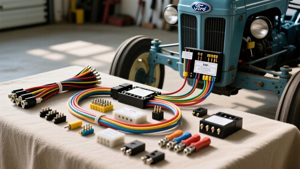
The Ford 8N tractor, produced from 1947 to 1952, remains one of the most iconic and widely restored agricultural machines in history. However, its original electrical system is notoriously fragile. Designed as a 6-volt, positive-ground system, the original cloth-braided wiring is highly susceptible to moisture, rodent damage, and brittle insulation failure. When restoring an 8N, replacing the deteriorated wiring with a modern, high-quality Ford 8N wiring harness is not just a cosmetic upgrade; it is a critical safety and reliability intervention.
Before beginning any installation, it is vital to understand the two distinct generations of the 8N electrical system. Early models (1947 to mid-1950) feature a front-mount distributor with a distinctive "crab cap" and a sweep-style ignition wire routing. Later models (mid-1950 to 1952) utilize an angled side-mount distributor. Your replacement harness must match your specific distributor configuration to ensure proper wire reach and loom routing. Furthermore, you must decide whether to retain the original 6V positive-ground architecture or perform a 12V negative-ground conversion, which is the industry standard for modern 8N restorations.
Choosing the Right Ford 8N Wiring Harness Kit
When sourcing a replacement harness, you will encounter two primary options: OEM-spec 6V replicas and 12V conversion harnesses. A standard 6V harness utilizes heavier gauge wires to compensate for the lower voltage and higher amperage required to crank the starter and power the lights. According to SAE J1128 Low Tension Primary Cable Standards, 6V systems require strict adherence to minimum AWG thresholds to prevent voltage drop.
- 6V Original Harness: Utilizes 10 AWG for the main battery feed, ammeter loop, and starter button circuit. Lighting and ignition circuits use 12 AWG or 14 AWG. Wire colors typically follow original Ford specs (Black for main hot, Red for switched power, Green for ignition/coil).
- 12V Conversion Harness: Often integrates heavier 8 AWG or 10 AWG feeds specifically routed for a 1-wire or 3-wire alternator (such as a Delco 10SI). It includes pre-integrated spade terminals for modern blade-style fuses and ballast resistor bypass loops.
For the most accurate wiring diagrams and historical reference, the N-Tractor Club Archives provide invaluable OEM schematics that map directly to aftermarket harness color codes.
Terminal Selection and Wire Preparation
A common failure point in amateur 8N restorations is the use of incorrect or poorly crimped terminals. The Ford 8N dash switches and ammeter utilize specific terminal sizes. Always use adhesive-lined heat-shrink ring and spade terminals to prevent moisture ingress and corrosion. Avoid vinyl-insulated crimp terminals, as the plastic sleeves can melt near the exhaust manifold or ceramic resistor block. Use a dedicated ratcheting crimp tool to ensure a gas-tight mechanical bond between the copper wire strands and the brass or nickel-plated terminal barrel.
Step-by-Step Harness Installation Procedure
Step 1: Dash Extraction and Bench Testing
Do not attempt to wire the dash while it is bolted to the tractor. Disconnect the battery (ground cable first). Remove the steering wheel using a proper puller to avoid damaging the steering box. Unbolt the dash panel and carefully extract it along with the instrument cluster. On a workbench, test the ammeter, ignition switch, and light switch for continuity and internal corrosion. If the ammeter shunt or internal coil shows high resistance, replace it before installing the new harness.
Step 2: Firewall Routing and Loom Protection
The main harness passes through the firewall behind the dash. Original 8N designs lacked dedicated rubber grommets, leading to chafing against the sheet metal. Install a modern rubber firewall grommet and apply dielectric grease to the harness jacket before feeding it through. Secure the harness to the firewall using stainless steel Adel clamps (P-clips) lined with EPDM rubber, ensuring the loom is kept at least two inches away from the exhaust manifold and steering column pivot points.
Step 3: Dash Component Integration
Connect the main battery feed to the ammeter. The Ford 8N uses an inline ammeter, meaning the full electrical load of the tractor passes through the dash gauge. Use 10 AWG wire with 3/8-inch ring terminals for the ammeter posts. Torque the nuts securely; a loose connection here will cause arcing, melting the plastic gauge housing and potentially causing a dash fire. Route the switched power from the ammeter to the ignition and light switches, securing the wires with cloth-friction tape to mimic the OEM aesthetic while providing modern abrasion resistance.
Ford 8N Wiring Harness Connection Matrix
| Source Component | Wire Color (Modern Replica) | AWG Size | Terminal Type | Destination |
|---|---|---|---|---|
| Battery (+) Post | Red (or Black OEM) | 10 AWG | 3/8" Ring | Ammeter (BAT Post) |
| Ammeter (GEN Post) | Red | 10 AWG | 3/8" Ring | Ignition Switch (BAT) |
| Ignition Switch (IGN) | Pink (or Green OEM) | 14 AWG | 1/4" Spade | Resistor Block / Coil (+) |
| Light Switch (Pwr In) | Red | 12 AWG | 1/4" Spade | Ignition Switch (BAT) Tap |
| Light Switch (Out) | Brown | 14 AWG | 1/4" Spade | Headlights & Taillight |
| Starter Button (In) | Red (Heavy Duty) | 10 AWG | 5/16" Ring | Solenoid / Battery Feed |
| Starter Button (Out) | Yellow (or Purple) | 10 AWG | 5/16" Ring | Starter Solenoid (S Post) |
Engine Bay Routing: Coil, Resistor, and Starter
Step 4: Front-Mount vs. Side-Mount Distributor Wiring
If you are working with a front-mount distributor, the ignition wire must be routed down the center of the engine block, passing through the specific retainer clip on the cylinder head. The terminal at the distributor cap is a unique sweep-style brass clip, not a standard spark plug wire boot. Ensure your harness includes the correct flat brass terminal. For side-mount distributors, route the 14 AWG ignition wire along the right side of the engine block, securing it away from the hot exhaust manifold. Use high-temperature fiberglass loom sleeving for the final six inches of the coil wire to prevent thermal degradation.
The 12-Volt Conversion: Alternator and Ballast Wiring
Most modern Ford 8N restorations utilize a 12V negative-ground system with a 1-wire Delco alternator. When installing a 12V conversion harness, the heavy 10 AWG alternator output wire must be routed directly to the battery side of the ammeter (or the starter solenoid battery post) to ensure the ammeter reads the charging current correctly. If you are using a 12V ignition coil that does not have an internal resistor, you must retain the original ceramic resistor block mounted on the back of the dash, or install an inline 1.5-ohm ballast resistor to drop the 14.4V alternator output down to the 9V required by the points and condenser. Bypassing the resistor on a standard coil will rapidly burn the ignition points and melt the harness.
For comprehensive community-tested 12V conversion schematics, Yesterday's Tractors Forums offer extensive user-generated diagrams that complement aftermarket harness instructions.
Troubleshooting Common 8N Harness Failures
Even with a brand-new Ford 8N wiring harness, tractors frequently suffer from electrical gremlins post-assembly. Use this diagnostic tree to resolve common issues:
- Symptom: Ammeter pegs to discharge when lights are turned on, but battery tests fully charged.
Cause: The ammeter is wired backward, or the alternator output wire is connected to the load side of the ammeter instead of the battery side. Fix: Swap the ammeter posts and verify the alternator main feed ties in before the ammeter shunt. - Symptom: No spark at the plugs, but 12V is present at the ignition switch.
Cause: Voltage drop across a painted dash or poor dash ground. The 8N dash grounds through the steering column and mounting bolts. Fix: Sand the paint off the dash mounting brackets and run a dedicated 12 AWG ground wire from the instrument cluster housing directly to the engine block. - Symptom: Starter button sparks heavily but engine does not crank.
Cause: The starter button is attempting to pass the full cranking amperage (200A+) without a relay. Fix: Install a standard Ford starter solenoid on the firewall. Use the dash button only to trigger the solenoid's "S" terminal with a low-amperage 14 AWG signal wire.
Conclusion
Installing a Ford 8N wiring harness requires patience, attention to historical detail, and strict adherence to modern electrical safety standards. By selecting the correct gauge wire, utilizing adhesive-lined terminals, and properly integrating the dash grounding and alternator feeds, you ensure that your 8N will start reliably and operate safely for decades to come. Always double-check your polarity and fuse protection before applying battery power for the first time.