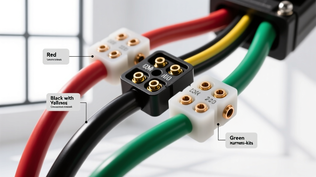
The GMT800 Fuel Pump Harness Failure Point
If you own a 1999-2006 GM GMT800 platform vehicle (Silverado, Sierra, Tahoe, Suburban), you are likely familiar with the notorious fuel pump pigtail failure. The OEM connector frequently suffers from terminal fretting corrosion, increased electrical resistance, and eventual melting of the plastic housing. When replacing a failing fuel sender or upgrading the delivery system, understanding the exact color codes, connector pinouts, and GM fuel pump wiring harness architecture is critical to preventing a stranded vehicle or, worse, an electrical fire.
This practical installation guide details the exact Delphi Packard connector specifications, wire color codes, and step-by-step harness fabrication techniques required to permanently resolve fuel pump voltage drop issues. By upgrading the harness kit with modern cross-linked insulation and proper open-barrel crimps, you ensure your high-pressure fuel pump receives the consistent voltage it requires to maintain optimal rail pressure.
GM Fuel Pump Connector Pinout and Color Codes
The standard GM 4-pin fuel tank connector utilizes a Delphi Metri-Pack series housing. The pins are arranged in a specific rectangular matrix. Miswiring the fuel level sender reference ground to the 12V pump feed will instantly fry the PCM's internal fuel level driver. Always verify your specific vehicle's service manual, but the following color codes and pin configurations represent the standard GMT800 V8 (4.8L, 5.3L, 6.0L) harness layout.
| Pin | Wire Color | Circuit Function | OEM AWG | Upgraded AWG | Circuit ID |
|---|---|---|---|---|---|
| A | Gray | Fuel Pump 12V Feed (from FP Relay) | 14 AWG | 12 AWG | 1020 |
| B | Black | Fuel Pump High-Current Ground | 14 AWG | 12 AWG | 150 |
| C | Purple | Fuel Level Signal to PCM/Cluster | 18 AWG | 18 AWG | 1587 |
| D | Black w/ White Stripe | Fuel Level Sender Reference Ground | 18 AWG | 18 AWG | 1588 |
Wire Gauge and Insulation Upgrades (SAE & ISO Specs)
Why upgrade from the OEM 14 AWG wire to a 12 AWG harness kit? The GMT800 fuel pump is located at the rear of the vehicle, requiring nearly 15 feet of wiring from the underhood relay center to the fuel tank. According to the SAE J1128 Low Tension Primary Cable Standard, a 14 AWG copper wire carrying 10 amps over a 30-foot round trip will experience a voltage drop of approximately 0.78 volts. While this seems minor, modern high-flow EFI pumps demand a minimum of 11.5V under heavy load to maintain 58 PSI of rail pressure. A voltage drop pushes the pump into amperage overdraw, generating excess heat and accelerating pump failure.
When fabricating or installing an aftermarket harness kit, ensure the wire insulation meets ISO 6722 Road Vehicle Cable Specifications. Specifically, use TXL or SXL (cross-linked polyethylene) insulation rather than standard PVC. TXL wire features a thinner insulation wall for easier routing through frame rails, while offering superior resistance to the extreme temperature fluctuations, road salt, and fuel vapors present beneath the vehicle chassis.
Step-by-Step Harness Replacement Guide
Replacing the GM fuel pump wiring harness requires precision. The most common mistake DIYers make is using generic closed-barrel butt splices and electrical tape, which inevitably fail due to underbody vibration and moisture intrusion.
Step 1: Depressurize and Isolate the System
Remove the fuel pump relay from the underhood fuse block. Crank the engine until it stalls to bleed off residual fuel pressure. Disconnect the negative battery terminal. Drop the fuel tank using a transmission jack, ensuring the bed of the truck is raised or removed if you are working on a crew-cab configuration where clearance is minimal.
Step 2: Extract the OEM Connector Pins
Do not cut the wires directly at the back of the OEM connector if you plan to reuse the housing. Use a Delphi Metri-Pack terminal extraction tool to depress the primary and secondary locking tangs. Pull the wires gently from the front of the connector. Inspect the housing for brown scorch marks; if the plastic is warped, you must install a complete pigtail replacement kit.
Step 3: Open-Barrel Crimping for Vibration Resistance
The Delphi connector utilizes open-barrel (F-crimp) terminals. For the 12 AWG gray and black wires, use Aptiv/Delphi part number 12191818 (or equivalent heavy-duty open-barrel terminals).
- Strip exactly 5/32" of insulation using precision wire strippers to avoid nicking the copper strands.
- Place the terminal in a ratcheting open-barrel crimper (such as the Titan 11500 or equivalent Delphi tool).
- Insert the wire so the strands are flush with the front of the wire crimp wings, and the insulation rests squarely in the insulation crimp wings.
- Squeeze the crimper until the ratchet releases. Perform a pull test; a proper mechanical crimp should withstand over 40 lbs of tensile force without slipping.
Step 4: Adhesive-Lined Heat Shrink and Loom Routing
Solder is brittle and will crack under chassis vibration. Instead, seal your inline splices using dual-wall, adhesive-lined heat shrink tubing. The inner meltable adhesive creates a waterproof seal that prevents capillary action from drawing moisture into the copper strands. Once spliced, wrap the entire harness run in split corrugated loom and secure it to the frame rail using UV-resistant zip ties, keeping the harness at least 4 inches away from the exhaust system to prevent TXL insulation melt-through.
Troubleshooting Decision Tree: Voltage & Ground Issues
Even with a new harness kit, underlying electrical faults can mimic a bad fuel pump. Use this diagnostic tree if the vehicle cranks but fails to start, or if the fuel pressure regulator reads below 50 PSI.
- Symptom: Fuel pump whines loudly, pressure is low, but 12V is present at the harness.
Cause: High resistance on the ground circuit (Pin B). The pump is completing the circuit through the fuel level sender ground, causing a voltage bottleneck.
Fix: Check the G401 ground point on the rear frame crossmember. Remove the bolt, sand the frame to bare metal, apply dielectric grease, and torque to 18 lb-ft. - Symptom: Fuel gauge reads 'Empty' but the engine runs perfectly.
Cause: Pin D (Black/White) reference ground is severed, or the fuel level sender float arm is binding.
Fix: Backprobe Pin C (Purple) with a multimeter. With the key ON, engine OFF, you should see a sweep from roughly 0.5V (Empty) to 3.5V (Full). If the voltage is pegged at 5V, the PCM is seeing an open circuit on the signal wire. - Symptom: Fuel pump relay clicks rapidly or melts.
Cause: Short to ground on the Gray 12V feed wire (Circuit 1020) between the relay and the harness connector, often caused by the wire rubbing against the driveshaft or a sharp frame edge.
Fix: Perform a continuity test from the relay socket output to chassis ground. Repair the chafe point and upgrade the loom protection.
By adhering to these GM color codes, utilizing proper open-barrel crimping techniques, and upgrading to 12 AWG TXL wire, your fuel pump wiring harness installation will outlast the vehicle itself. For further reference on terminal retention forces and cavity plug requirements, consult the Aptiv Connection Systems catalog to ensure your harness kit meets OEM engineering tolerances.