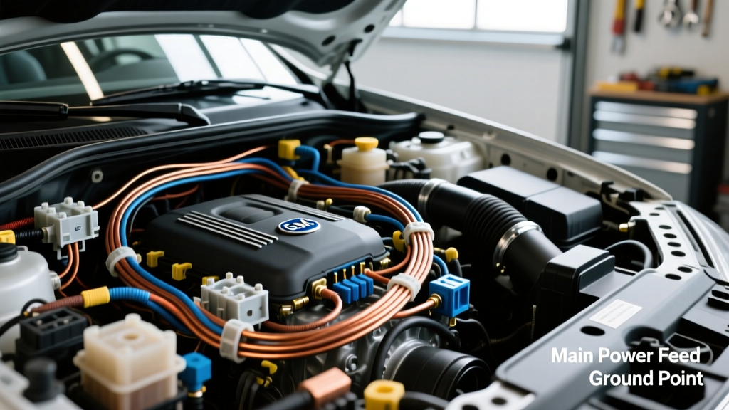
Pre-Installation Planning and Harness Selection
Swapping a GM LS V8 into a classic muscle car, truck, or import platform requires far more than just fabricating motor mounts and dropping in the engine. The nervous system of your swap—the LS engine swap wiring harness—dictates whether your project fires up on the first key turn or chases electrical gremlins for months. Before cutting a single wire, you must decide between modifying an original equipment manufacturer (OEM) harness or purchasing a dedicated standalone aftermarket swap harness.
OEM harnesses from donor vehicles (like a 1999-2002 Camaro or 2003 Silverado) are cost-effective but require extensive rework. You must physically remove the Vehicle Anti-Theft System (VATS) wiring, strip out unnecessary emissions circuits (EGR, EVAP, secondary O2 sensors), and extend the main bulkhead to reach your new cabin or firewall-mounted PCM location. Conversely, aftermarket standalone harnesses from manufacturers like Painless Performance or Holley come pre-loomed, stripped of emissions clutter, and feature clearly labeled, unterminated ends for custom integration. Regardless of your choice, understanding General Motors' Gen III and Gen IV PCM pinouts and adhering to SAE J1128 standards for primary automotive cable is non-negotiable for a reliable installation.
Essential Wire Specifications and Circuit Sizing
Using the correct wire gauge and insulation type is critical. The engine bay environment exposes wiring to extreme heat, vibration, and corrosive fluids. Always use cross-linked polyethylene (XLPE) insulated wire, such as GXL or TXL, which offers superior heat and abrasion resistance compared to standard PVC wire. Below is the foundational specification chart for the primary circuits in a standard 4-wire Gen III/IV LS PCM setup.
| Circuit Function | Minimum AWG | Typical GM OEM Color | PCM Connector / Pin |
|---|---|---|---|
| Main PCM Battery Power | 10 AWG | Orange | Red (C2) Pin 20 |
| PCM Ignition (Switched 12V) | 12 AWG | Pink | Blue (C1) Pin 19 / Green (C3) Pin 20 |
| Injector Power Feed | 14 AWG | Pink/White | Fused 12V Source (Not PCM) |
| PCM Main Grounds | 10 AWG | Black/White | Blue (C1) Pins 1, 21, 40, 41, 60, 61 |
| Fuel Pump Relay Control | 16 AWG | Dark Green/White | Blue (C1) Pin 18 (Ground Side) |
| Upstream O2 Signal | 20 AWG | Tan | Black (C4) Pins 8, 9 |
| Alternator 'L' Terminal Exciter | 18 AWG | Brown | Red (C2) Pin 15 |
Step-by-Step LS Engine Swap Wiring Harness Routing
Step 1: ECU Placement and Main Bulkhead Routing
The Powertrain Control Module (PCM) is highly sensitive to heat and moisture. In most classic car swaps, the optimal location is inside the cabin, mounted under the dash or kick panel. If you must mount the PCM in the engine bay, fabricate a sealed, heat-shielded enclosure away from exhaust headers. When routing the main bulkhead connectors (the large 80-way plugs) through the firewall, always use a reinforced rubber grommet. Apply a dielectric silicone grease to the connector seals before mating them to the PCM to prevent moisture ingress and terminal corrosion. Maintain a minimum bend radius of five times the wire bundle's outer diameter to prevent internal copper strand fracturing.
Step 2: Injector and Coil Pack Sub-Harness Dressing
The injector and coil pack sub-harness sees the most vibration and heat exposure. Route the harness down the center of the intake manifold (for truck manifolds) or along the valve cover rails (for car manifolds). Secure the harness using nylon cable ties anchored to existing intake manifold bolts, avoiding zip-ties directly over sharp casting edges. Use high-temperature split loom or woven Techflex sleeving. Crucially, leave a 2-inch service loop of slack near each injector connector. LS injectors use USCAR-style connectors; ensure the secondary locking tabs are fully engaged to prevent a lean misfire caused by a vibrating connector.
Step 3: Sensor Integration (MAP, TPS, and O2)
Sensor wiring requires careful routing away from high-voltage ignition components to prevent Electromagnetic Interference (EMI). Route the Throttle Position Sensor (TPS) and Manifold Absolute Pressure (MAP) sensor wires on the opposite side of the engine bay from the coil pack main feed. Upstream Oxygen (O2) sensors generate a low-voltage (0-1V) analog signal that is highly susceptible to noise. Keep O2 signal wires (typically Tan and Purple for Bank 1/Bank 2) at least 4 inches away from alternator output cables and ignition spark plug wires.
Power, Grounding, and Relay Integration
The single most common cause of LS swap drivability issues—ranging from random stalling to erratic idle—is inadequate grounding. The LS PCM utilizes internal low-side drivers for many components, meaning it relies entirely on the quality of the chassis and engine grounds to complete circuits.
The 'Big Three' Grounding Strategy
- Engine Block to Chassis: Use a minimum of 1/0 AWG flexible braided copper strap. Attach one end to a clean, bare metal surface on the cylinder head or engine block, and the other to the vehicle's main chassis rail. Sand away all powder coating, rust, and primer at the contact points.
- PCM Dedicated Grounds: The Blue connector (C1) houses the primary PCM grounds on pins 1, 21, 40, 41, 60, and 61. These six 10 AWG black/white wires must be terminated into a single, heavy-duty ring terminal and bolted directly to the engine block or a dedicated, clean chassis ground stud. Do not daisy-chain these grounds with interior accessories.
- Transmission/ bellhousing Ground: A 4 AWG ground strap from the bellhousing to the chassis ensures the starter motor return current does not seek a path through the PCM or sensor grounds, which can instantly fry internal PCM drivers.
Fuel Pump and Alternator Relay Setup
The LS PCM does not supply direct 12V power to high-draw components; it acts as a ground-side switch. For the fuel pump, the PCM grounds Pin 18 on the Blue connector to activate a standard 30A ISO relay. Wire the relay coil's positive terminal to a fused ignition source, and the relay's switched 12V output to the fuel pump using 12 AWG wire.
For the alternator, GM CS130, CS144, and AD230 alternators require an 'L' terminal exciter signal to begin charging. The PCM provides this via Pin 15 on the Red connector. However, to prevent voltage back-feeding into the PCM when the key is turned off, you must install a 1-Amp blocking diode or a 560-ohm resistor in-line on the Brown exciter wire. Failing to do this will result in the alternator back-feeding the ignition circuit, causing the engine to 'run on' after the key is removed, or worse, destroying the PCM's internal voltage regulator driver.
Instrument Cluster and Tachometer Signal Conversion
Classic vehicles and early imports utilize 12V pulse tachometers driven by the negative side of the ignition coil. The LS PCM, however, outputs a 5V square-wave tachometer signal from Pin 10 on the Blue connector. Connecting a classic 12V tach directly to this 5V PCM output will result in a dead gauge or erratic needle bounce. To resolve this, you must integrate a signal pull-up module, such as a Dakota Digital SGI-5C, or build a simple discrete circuit using a 10k-ohm pull-up resistor to a 12V source and an NPN transistor to step the 5V square wave up to the 12V pulse required by analog gauges. Always consult your specific GM Helm Inc service manual for the exact pulse-per-mile (PPM) and tachometer pulse settings configurable within the PCM's HP Tuners software.
Common LS Swap Wiring Pitfalls and Troubleshooting
- Crank, No Start (VATS Lockout): If the engine cranks but injectors do not pulse, the Vehicle Anti-Theft System is likely still active in the PCM's operating system. You must use tuning software to disable VATS or install a standalone VATS bypass module that simulates the correct resistor pellet voltage to the PCM.
- Idle Surge or Hanging RPM: Often caused by a TPS voltage mismatch or a vacuum leak, but electrically, it can stem from a poor 5V reference ground. Ensure the Black wire on the TPS connector shares the exact same ground node as the PCM's dedicated sensor ground.
- Alternator Whine in Audio System: Caused by routing the main alternator charge wire (which carries high-amperage AC ripple) parallel to the RCA or audio signal wires. Reroute the 4 AWG alternator charge wire directly to the battery positive terminal, completely separate from the firewall harness routing.
Authoritative References
For deep-dive pinout diagrams, torque specifications for PCM connector retaining bolts, and factory wiring schematics, always refer to the official GM Helm Inc Service Documentation corresponding to your donor vehicle's year and model. For aftermarket harness integration and relay sizing, consult the technical bulletins provided by Painless Performance Products. Adherence to SAE J1128 wire standards ensures your harness will survive the harsh under-hood environment of your swap.