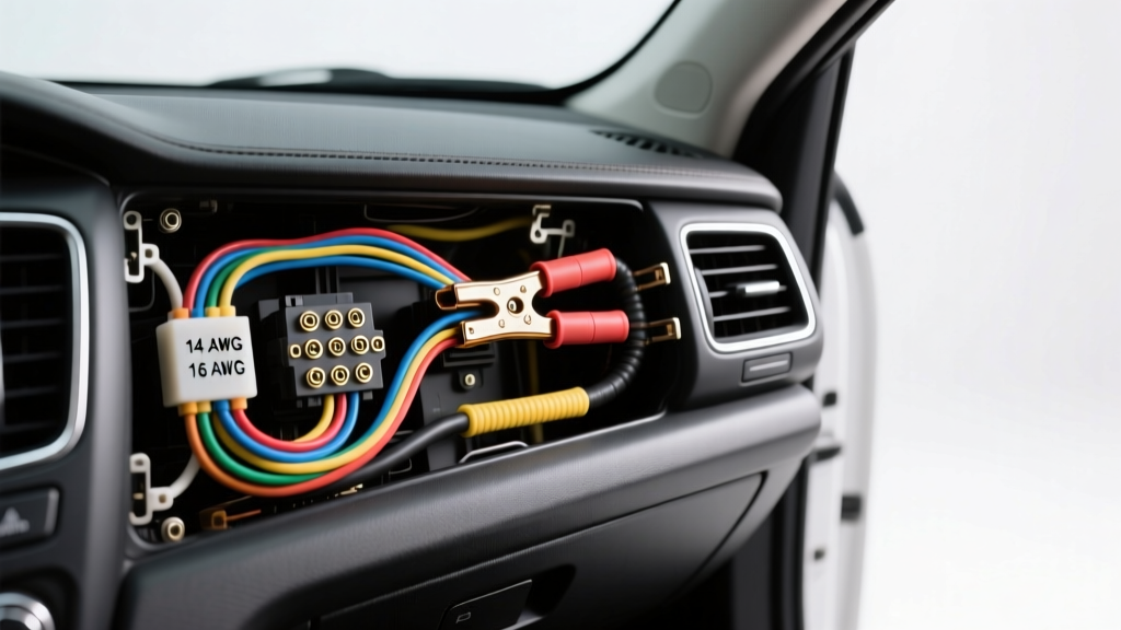
The Hardwire Dilemma: When Adapters Aren't an Option
In an ideal world, every car audio installation utilizes a plug-and-play OEM-to-ISO wiring harness adapter. However, automotive electricians and DIYers frequently encounter scenarios where adapters are unavailable, obsolete, or physically destroyed. Whether you are restoring a classic vehicle with a degraded factory harness, performing a junkyard engine-and-dash swap, or integrating a custom marine head unit into a street car, knowing how to install a radio without a wiring harness adapter is a critical skill. Hardwiring directly to the factory loom requires a deep understanding of circuit mapping, wire gauge transitions, and vibration-resistant termination methods.
Direct splicing introduces failure points if executed improperly. The automotive environment is hostile; cables are subjected to extreme temperature cycling, high-frequency vibration, and corrosive humidity. According to SAE J1128 standards for low-tension primary cables, automotive wire insulation is designed to resist specific thermal and chemical stressors, meaning your splice must match or exceed the integrity of the factory loom. This guide compares the best connection products for direct-wire installs and provides a masterclass on executing a safe, reliable hardwire integration.
Product Comparison: Selecting the Right Wire Connectors
When bypassing a harness adapter, the connectors you choose dictate the longevity of your installation. Below is a comparison of common splicing products, evaluated on pull-out strength, vibration resistance, and moisture ingress protection.
1. Solder Seals (Adhesive-Lined Heat Shrink Solder Sleeves)
Solder seals combine a ring of low-temperature solder with an adhesive-lined polyolefin heat shrink tube. When heated, the solder melts to fuse the copper strands, while the adhesive melts to create a waterproof, airtight seal. Verdict: The gold standard for permanent, moisture-proof connections, especially in door jambs or convertible trunks. However, they are time-consuming and require a quality heat gun, not a lighter.
2. Nylon Insulated Ratcheted Crimps (Butt Connectors)
Using a nylon-insulated butt connector crimped with a ratcheting tool (such as an IWISS or Titan) creates a cold-weld gas-tight connection. Verdict: Excellent for behind-the-dash applications where space is tight and heat guns are a fire hazard. Must use the correct die (usually red for 18-16 AWG).
3. Posi-Tap and Posi-Twist Connectors
These mechanical screw-down connectors pierce or cap wires without requiring stripping tools. Verdict: Great for temporary diagnostics or tapping into thick power wires, but far too bulky to fit behind a standard Single-DIN or Double-DIN radio cage. Not recommended for the final radio harness termination.
4. T-Taps and Scotch Locks (The "Never Use" Category)
Scotch locks use a metal blade to cut through the wire insulation and bite into the copper strands. Verdict: Never use these. They sever up to 30% of the copper strands, creating a high-resistance bottleneck that generates heat. Furthermore, they leave the puncture site exposed to oxygen, guaranteeing green corrosion and eventual open-circuit failure within 12 months.
Connector Selection Matrix
| Connector Type | Pull-Out Force | Vibration Resistance | Moisture Seal | Recommended Application |
|---|---|---|---|---|
| Adhesive Solder Seal | > 35 lbs | Excellent | Waterproof | Permanent loom repairs, marine, exterior |
| Nylon Ratcheted Crimp | > 20 lbs | Excellent | Moisture Resistant | Behind-dash radio harnesses, tight spaces |
| Non-Insulated Crimp + Tape | > 15 lbs | Poor | None | None (Avoid in automotive) |
| Scotch Lock / T-Tap | < 5 lbs | Very Poor | None | None (Strictly prohibited) |
Standard CEA-310 Pinout and AWG Specifications
Before making any cuts, you must understand the aftermarket radio standard. The Consumer Technology Association (CTA) maintains the CEA-310 standard (formerly EIA-310), which dictates the universal color code for aftermarket head units. When hardwiring, you will be mating these aftermarket colors to the vehicle-specific factory colors.
| CEA-310 Wire Color | Function | Typical AWG | Hardwiring Notes |
|---|---|---|---|
| Yellow | 12V Constant (Memory) | 16 AWG | Connect to battery-backed fuse (e.g., interior lights, horn). |
| Red | 12V Switched (Ignition) | 16 AWG | Connect to ignition-on or accessory fuse. Do NOT connect to CANbus data lines. |
| Black | Chassis Ground | 16 AWG | Must terminate to bare, unpainted metal chassis or factory ground bus. |
| Orange / Dimmer | Illumination / Dimmer | 18 AWG | Connect to factory headlight dimmer switch circuit (usually 0-12V PWM or analog). |
| Blue / White | Amplifier Turn-On | 18 AWG | Outputs 12V when radio is on. Max draw usually 300mA. |
| White / White-Black | Front Left Speaker (+/-) | 18 AWG | Ensure factory wiring is not amplified (common in Bose/JBL systems). |
| Gray / Gray-Black | Front Right Speaker (+/-) | 18 AWG | Verify phase with a 1.5V AA battery pop-test if diagrams are missing. |
| Green / Green-Black | Rear Left Speaker (+/-) | 18 AWG | Check for factory crossover networks inline with the speaker. |
| Purple / Purple-Black | Rear Right Speaker (+/-) | 18 AWG | Never ground the negative speaker wire on amplified factory systems. |
Step-by-Step: How to Install a Radio Without a Wiring Harness Adapter
Follow this exact sequence to ensure a safe, noise-free, and reliable direct-wire installation.
Phase 1: Circuit Mapping and Verification
- Disconnect the Battery: Always disconnect the negative battery terminal before cutting into a factory loom to prevent shorting the 12V constant wire to the CANbus or data lines, which can fry the Body Control Module (BCM).
- Identify Power and Ground: Use a Digital Multimeter (DMM). Set it to DC Voltage. Reconnect the battery temporarily. Probe the factory plug: the wire showing 12.4V with the key OFF is your Constant (Yellow). The wire showing 12.4V only with the key in ACC/ON is your Switched (Red). The wire showing 0 ohms to bare chassis metal is Ground (Black).
- Map the Speakers: If factory wiring diagrams are unavailable, use the "AA Battery Test". Strip the suspected speaker wires. Briefly tap the positive and negative terminals of a 1.5V AA battery to the wire pairs. Listen for a static "pop" from the cabin speakers to confirm location and polarity.
Phase 2: Prepping and Splicing the Wires
- Stagger Your Cuts: Never cut all factory wires at the exact same point. Stagger your cuts by 1 to 2 inches. If the harness is ever pulled, staggered splices will not create a single, massive bulge that prevents the radio from sliding into the DIN cage, and it prevents a single short-circuit if the tape fails.
- Strip with Precision: Use automatic wire strippers calibrated for 18 and 16 AWG. Avoid nicking the copper strands, which reduces tensile strength and creates a hot-spot for resistance.
- The Gauge-Mismatch Trick: Aftermarket radios use 16 AWG for power, but factory Japanese and European cars often use 18 or 20 AWG for the same circuits. When crimping a 16 AWG aftermarket wire to an 18 AWG factory wire inside a 16-14 AWG butt connector, fold the 18 AWG factory wire back over itself (doubling its cross-section) before inserting it into the crimp barrel. This ensures a gas-tight mechanical bite.
- Crimp and Inspect: Use a ratcheting crimp tool. The ratchet must complete the full cycle. Tug both wires firmly (at least 10 lbs of force) to verify the cold-weld.
Phase 3: CANbus and RAP Considerations
Modern vehicles (specifically GM, Chrysler, and Ford post-2006) utilize Class 2 CAN, GMLAN, or MS-CAN networks to communicate the ignition status to the radio, known as Retained Accessory Power (RAP). You cannot hardwire a standard aftermarket radio directly to a CANbus data wire. Doing so will result in the radio failing to turn on, or worse, backfeeding 12V into the data bus and corrupting network packets. If your vehicle uses RAP, you must install a CANbus-to-12V decoder module (like an Axxess XSVI or PAC RP4) to translate the digital data signal into an analog 12V switched output for your aftermarket Red wire.
Troubleshooting Direct-Wire Installs
- Alternator Whine (Ground Loop): If you hear a whining noise that pitches up with engine RPM, your ground is insufficient. Do not rely on the factory radio ground wire if it shares a bus with high-draw components. Run a dedicated 16 AWG or 14 AWG ground wire directly from the radio's black wire to a clean, sanded metal bolt on the chassis crossmember.
- Parasitic Battery Draw: If your car battery dies overnight, you have likely swapped the Constant (Yellow) and Switched (Red) wires, or you have tapped the "Constant" into a circuit that stays powered by the BCM's sleep-mode logic. Use your DMM in series with the negative battery terminal to measure amperage draw. A properly wired radio should draw less than 5mA in sleep mode.
- Speaker Distortion / Clipping: If hardwiring into a vehicle with a factory amplified system (e.g., Bose, JBL, Infinity), you are tapping into the post-amplifier speaker wires. Sending an already-amplified, high-level signal into the aftermarket radio's pre-amp or speaker-level inputs will cause severe clipping and potentially blow the head unit's internal IC. You must use a Line Output Converter (LOC) or bypass the factory amplifier entirely by running new 16 AWG speaker wire directly from the radio to the door speakers.
Final Loom Security
Once all connections are verified and tested, wrap the entire splice bundle in Tesa 51036 PET cloth tape or corrugated split loom tubing. Never use standard vinyl electrical tape under the dash; the adhesive melts in summer heat, unraveling the bundle and exposing bare copper to the metal dashboard sub-frame, leading to dead shorts and blown fuses. Secure the harness to the factory wiring loom using nylon zip-ties, ensuring enough slack for the radio to slide in and out of the dash for future maintenance or GPS antenna routing.
For more comprehensive guides on automotive electrical standards and connector selections, reference the Crutchfield Car Audio Wiring Guide and always verify your specific vehicle's pinout via factory service manuals before cutting a single wire.