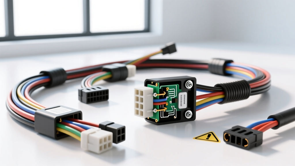
The Hidden Dangers of Poor Wiring Harness Execution
Building or installing custom and aftermarket wiring harnesses is one of the most critical phases of any engine swap, restomod, or custom vehicle build. While routing wires and snapping connectors together may seem straightforward, the engine bay is a hostile environment characterized by extreme heat, high vibration, and corrosive elements. A single oversight in wire gauge selection, grounding topology, or termination methodology can lead to catastrophic electrical fires, parasitic battery drains, or the instantaneous destruction of a $2,000 ECU.
At Autoflow Wire, we have analyzed hundreds of failed harness returns and post-installation troubleshooting logs. The following guide details the most severe, yet entirely preventable, safety mistakes made when fabricating and installing wiring harnesses, complete with SAE standards and actionable corrective protocols.
Mistake #1: The 'Daisy Chain' Grounding Fallacy
The most pervasive error in custom wiring harnesses is the 'daisy chain' ground topology. This occurs when a builder routes a single ground wire from the ECU to the fuel pump relay, then to the ignition coils, and finally to a single chassis ground point. This creates a high-resistance series circuit. When the fuel pump draws 15 amps, the voltage drop across the shared ground wire alters the reference voltage for the ECU and ignition coils, leading to erratic idle, misfires, or ECU logic faults.
The Star Ground Protocol
Always utilize a 'star ground' or dedicated ground bus topology. High-amperage components (fuel pumps, cooling fans, starter solenoids) must have dedicated ground paths directly to the engine block or chassis. Low-amperage sensor grounds should be routed to a dedicated ECU sensor ground bus.
- Surface Prep: Never ground to painted metal or powder-coated surfaces. Use a 3M Roloc disc to expose bare steel or aluminum.
- Hardware: Use stainless steel or zinc-plated steel ring terminals with an internal star washer to bite into the chassis. Avoid aluminum ring terminals on steel chassis due to galvanic corrosion.
- Torque Specifications: An M8 ground stud secured to a steel chassis requires 15-20 Nm (11-15 lb-ft) of torque. An M6 stud requires 8-10 Nm. Under-torquing allows micro-movements that break the oxide layer, causing arcing and heat.
- Sealing: Coat the terminated ground stud with di-electric grease or a dedicated liquid electrical tape to prevent moisture ingress and subsequent rust jacking.
Mistake #2: Wire Gauge and Fuse Rating Mismatches
A fundamental rule of automotive electrical safety is that the fuse protects the wire, not the component. If a component draws 12 amps, but the wiring harness utilizes 18 AWG wire protected by a 30-amp fuse, a short circuit will cause the 18 AWG wire to melt and ignite long before the 30-amp fuse blows. According to SAE J1128 standards for low-tension primary cables, wire gauge must be matched to the maximum continuous current load and the length of the circuit to account for voltage drop.
SAE J1128 Wire Gauge to Fuse Sizing Matrix (GXL/TXL Wire)
| Wire Gauge (AWG) | Max Continuous Amps | Recommended Fuse Size | Typical Harness Application |
|---|---|---|---|
| 18 AWG | 6 Amps | 5A or 7.5A | ECM sensor feeds, dashboard illumination, low-draw LEDs |
| 16 AWG | 10 Amps | 10A | Injector circuits, interior dome lights, horn relay trigger |
| 14 AWG | 15 Amps | 15A | Headlight low beams, fuel pump relay feed, 12V accessory sockets |
| 12 AWG | 20 Amps | 20A | High-beam headlights, power window motors, ABS module feeds |
| 10 AWG | 30 Amps | 30A | Main ECU power feeds, high-speed cooling fan circuits, ignition coils |
| 8 AWG | 40-50 Amps | 40A or 50A | Alternator B+ output, main starter solenoid distribution block |
Note: For runs exceeding 15 feet, step up one AWG size to compensate for voltage drop, especially on critical ECU and fuel pump circuits where a drop below 11.5V can cause system failure.
Mistake #3: Soldering in High-Vibration Engine Bay Zones
While soldering is acceptable for static, interior dashboard harnesses, it is a critical safety hazard in the engine bay. Solder wicks into the wire strands via capillary action, creating a rigid, inflexible section of wire. In high-vibration environments—such as near the engine block, suspension mounts, or steering column—this rigid transition point becomes a stress riser. Over time, the copper strands fatigue and snap inside the insulation, leading to intermittent open circuits or high-resistance arcing.
Furthermore, standard rosin-core solder melts at approximately 183°C (361°F). Under-hood temperatures near exhaust manifolds can easily exceed this threshold during sustained high-RPM driving or when the vehicle is parked and heat-soaking.
The Open-Barrel Crimp Standard
Professional wiring harnesses rely on open-barrel, F-style crimps using ratcheting crimpers (such as TE Connectivity AMP or Asta tools). A proper crimp creates a cold-weld, gas-tight connection where the copper strands are compressed so tightly that oxygen cannot enter to cause corrosion. When terminating weather-sealed connectors like the Aptiv Metripack 2.8 or Deutsch DT series, always ensure the wire insulation crimp and the conductor crimp are distinctly separated and that the terminal bellmouth is visible.
Mistake #4: Ignoring Thermal and Abrasion Clearances
Routing a wiring harness too close to exhaust components is a guaranteed recipe for a melted harness and an engine bay fire. Standard cross-linked polyethylene (TXL/GXL/SXL) wire insulation is rated for continuous use up to 125°C, but direct radiant heat from a cast-iron exhaust manifold (which can exceed 400°C) will rapidly degrade the insulation, exposing bare copper to the chassis.
- Clearance Rule: Maintain a minimum 6-inch clearance between any wiring harness and exhaust manifolds, headers, or downpipes.
- Thermal Protection: If routing near heat sources is unavoidable, the harness must be encased in T3004 fiberglass sleeving or high-temp reflective loom (rated to 500°F+).
- Chafing Points: Anywhere a harness passes through a sheet metal firewall or bulkhead, a rubber grommet is mandatory. Use split-loom tubing secured with Tesa 51036 PET cloth tape (never use standard vinyl electrical tape, which unspools and turns into a sticky residue under hood heat) to protect against sharp bracket edges.
Harness Failure Diagnostic Decision Tree
When a newly installed wiring harness exhibits erratic behavior, use this diagnostic matrix to isolate the failure mode before replacing components.
| Symptom | Probable Harness Cause | Diagnostic Action & Fix |
|---|---|---|
| ECU resets when cooling fans engage | Shared ground path causing voltage spike/drop | Measure voltage drop across ECU ground pin to battery negative while fans cycle. If >0.05V, run dedicated 10 AWG ground to block. |
| Intermittent misfire under heavy load | Ignition coil harness tension or micro-fractured crimp | Perform a 'wiggle test' on coil connectors while monitoring live misfire data. Re-crimp using proper ratcheting tool if resistance fluctuates. |
| Fuel pump whines and drops pressure | Undersized wire gauge causing voltage drop at pump | Check voltage at fuel pump connector under load. If below 12.0V, upgrade feed and ground circuits from 14 AWG to 10 AWG. |
| Parasitic draw after vehicle is off | Switched 12V circuit wired to constant B+ source | Verify OEM color codes (e.g., GM Pink is switched ignition, Red is constant B+). Pull fuses sequentially to isolate the offending harness branch. |
Final Safety Directives
Building reliable wiring harnesses requires patience, precision tooling, and strict adherence to automotive electrical standards. Never compromise on wire quality; always specify SAE J1128 compliant GXL or TXL wire rather than cheap PVC alternatives found in hardware stores. By respecting grounding topology, matching fuse ratings to wire capacity, and utilizing proper cold-weld crimping techniques, you ensure that your vehicle's electrical nervous system remains safe, reliable, and fire-free for thousands of miles.