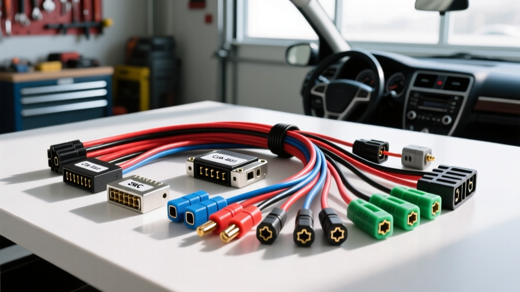
Decoding the Aftermarket Radio Wiring Harness Diagram
Transitioning from a legacy analog head unit to a modern digital media receiver requires more than just matching wire colors. While a basic aftermarket radio wiring harness diagram provides a foundational roadmap for connecting power, ground, and speakers, modern vehicle integration demands a deeper understanding of multiplexed data networks, steering wheel control (SWC) resistor ladders, and high-current power routing. Relying solely on generic diagrams often leads to parasitic battery drains, alternator whine, and blown internal traces.
At Autoflowwire, we approach harness integration from an engineering perspective. This advanced technical deep dive dissects the CTA-2003 (formerly CEA) standard, analyzes voltage drop across standard 18 AWG circuits, and outlines the protocol-level integration required for late-model CAN-bus vehicles.
The CTA-2003 Standard: Color Codes and AWG Specifications
The Consumer Technology Association (CTA) established the 2003 standard to unify aftermarket mobile electronics wiring. However, off-the-shelf harness adapters often utilize undersized 20 AWG or 22 AWG wire for power circuits to cut manufacturing costs, leading to severe voltage drop when powering modern amplifiers or high-draw receivers.
| Wire Color | Function | Standard AWG | Recommended AWG | Max Continuous Current |
|---|---|---|---|---|
| Yellow | 12V Constant (B+ / Memory) | 18 AWG | 12 AWG | 15A (Up to 25A for high-draw) |
| Red | 12V Switched (ACC / Ignition) | 18 AWG | 14 AWG | 10A |
| Black | Chassis Ground | 18 AWG | 12 AWG | 25A+ |
| Blue w/ White Stripe | Amplifier Remote Turn-On | 22 AWG | 18 AWG | 2A (Trigger only) |
| Orange | Illumination (12V+) | 22 AWG | 22 AWG | 1A |
| Orange w/ White Stripe | Dimmer (Variable 0-12V) | 22 AWG | 22 AWG | 1A |
Speaker Wire Phase and Polarity Matrix
Standard speaker outputs utilize a solid color for positive (+) and a color with a black tracer for negative (-). Maintaining absolute phase coherence is critical; reversing polarity on a single driver causes destructive acoustic interference, severely degrading mid-bass response.
- Front Left: White (+) / White w/ Black Stripe (-)
- Front Right: Gray (+) / Gray w/ Black Stripe (-)
- Rear Left: Green (+) / Green w/ Black Stripe (-)
- Rear Right: Purple (+) / Purple w/ Black Stripe (-)
High-Current Routing and Voltage Drop Mitigation
A common failure mode in aftermarket installations is voltage starvation. Modern receivers with built-in 4x50W MOSFET amplifiers can draw upwards of 15 amps at peak transient volumes. According to SAE J1128 standards for low-tension cables, an 18 AWG copper wire has a resistance of approximately 6.385 ohms per 1,000 feet. In a typical 10-foot run (20 feet round-trip for power and ground), drawing 15A will result in a voltage drop of nearly 1.9V. This drops the head unit's operating voltage below the 11.8V threshold, triggering internal protection circuits and causing the unit to reboot.
The Proper Grounding Protocol
Never rely on the factory radio harness ground wire for high-current aftermarket units. Factory grounds are often daisy-chained through the dash frame, introducing ground loop impedance. To eliminate alternator whine and ensure clean DC power:
- Locate a dedicated, unpainted structural chassis bolt within 18 inches of the head unit.
- Use a wire brush to remove all primer, paint, and rust down to bare steel.
- Terminate the 12 AWG black ground wire with a closed-loop ring terminal, crimped using a ratcheting hex-crimper.
- Apply dielectric grease over the terminal to prevent galvanic corrosion, and torque to the vehicle manufacturer's specification (typically 8-12 Nm for M6 bolts).
CAN-Bus Integration and Data Wake Signals
In late-model vehicles (typically 2008+ for GM/Ford, 2011+ for FCA/Stellantis), the traditional Red (ACC) 12V switched wire no longer exists. The factory radio is powered via a constant 12V B+ and is "woken up" by a high-speed CAN-bus data message. Standard aftermarket radio wiring harness diagrams do not account for this, requiring a data interface module (such as those documented by iDatalink Maestro or Axxess).
Class 2 GMLAN vs. CAN-H / CAN-L
When splicing into the vehicle's OBD-II data lines or the factory radio harness for SWC retention, you must identify the correct network topology:
- CAN-High (CAN-H): Typically operates between 2.5V (recessive) and 3.5V (dominant).
- CAN-Low (CAN-L): Typically operates between 2.5V (recessive) and 1.5V (dominant).
- GMLAN (Single Wire CAN): Operates at 0V (recessive) and 4V (dominant). Common in older GM vehicles.
Warning: Connecting a standard 12V test light or multimeter in current-measuring mode across CAN-bus pins will instantly blow the transceiver chip on the vehicle's Body Control Module (BCM). Always use a high-impedance digital multimeter or an automotive oscilloscope to verify data network integrity.
Steering Wheel Control (SWC) Resistor Ladders
For vehicles utilizing analog SWC, the factory harness uses a resistor ladder network. Pressing a steering wheel button changes the resistance on the Key 1 or Key 2 circuit. The aftermarket interface module measures this voltage drop (via an internal 5V reference and ADC) to map the button press. If your wiring diagram indicates two SWC wires (usually Key 1 and Key 2), they must be connected to the corresponding interface wires. If the vehicle uses a single-wire resistive system, the second interface wire is left isolated and insulated.
Advanced Troubleshooting Decision Tree
When an installation deviates from the expected behavior of the aftermarket radio wiring harness diagram, use this diagnostic matrix to isolate the fault.
Symptom: Head Unit Loses Memory (Presets/Clock) Every Ignition Cycle
- Cause A: Swapped Yellow (Constant) and Red (Switched) wires.
- Fix: Verify B+ at the Yellow wire with the key OFF. Swap pins at the ISO connector if necessary.
- Cause B: High resistance on the constant 12V feed due to a blown inline fuse or corroded battery tap.
- Fix: Perform a voltage drop test across the Yellow wire circuit under load. Resistance should be < 0.1V.
Symptom: Alternator Whine (High-Pitched Noise Modulating with RPM)
- Cause A: Ground loop caused by sharing a ground point with high-current accessories or using the factory thin-gauge ground wire.
- Fix: Run a dedicated 12 AWG ground directly to the chassis. Ensure RCA cables are routed on the opposite side of the vehicle from power cables.
- Cause B: Pinched speaker wire shorting to the chassis, causing the internal MOSFET to dump noise into the audio path.
- Fix: Disconnect all speaker wires at the harness. Test with a single known-good speaker. Re-terminate any damaged speaker wire insulation.
Symptom: Vehicle Battery Drains Overnight (Parasitic Draw)
- Cause A: Aftermarket interface module failing to enter sleep mode due to improper CAN-bus termination or miswired ACC trigger.
- Fix: Verify the interface module's data connection. Ensure the Red (ACC) wire on the radio is NOT connected to a constant 12V source in a CAN-bus vehicle; it should be driven by the interface module's data-triggered ACC output.
Professional Certification and Best Practices
Proper interpretation of wiring diagrams and adherence to electrical safety standards is the hallmark of a professional installer. For those looking to validate their knowledge in mobile electronics, including advanced harness fabrication and CAN-bus diagnostics, the Mobile Electronics Certification Program (MECP) offers industry-recognized credentials that cover everything from basic 12V theory to advanced network topology. Always verify pinouts with a digital multimeter before applying power, as factory wiring colors can vary by trim level, production month, and optional audio packages (e.g., Bose, Harman Kardon, or JBL amplified systems require specialized line-output converters to bypass factory DSP).