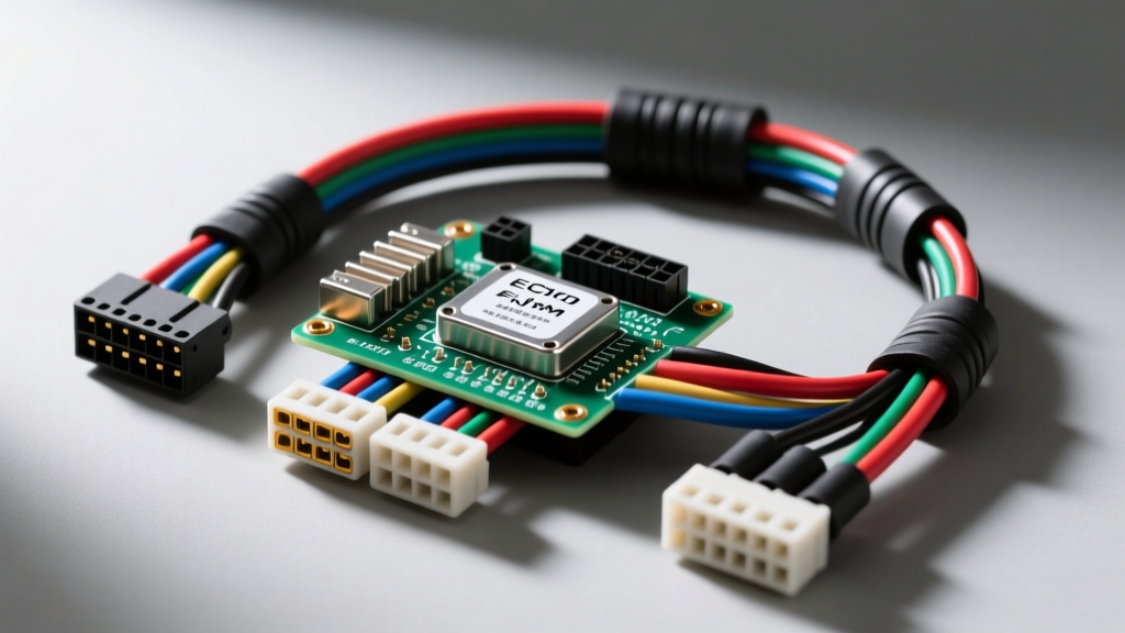
Architecture of the Modern Engine Control Module Wiring Harness
The evolution of the engine control module wiring harness represents one of the most significant shifts in automotive electrical engineering. Early engine management systems relied on simple, low-density power distribution looms. Today, the modern ECM harness is a complex, high-frequency data network tasked with transmitting microsecond-level sensor pulses, high-speed CAN-bus communications, and high-amperage injector driver signals simultaneously. When performing an engine swap, building a custom harness, or diagnosing a complex driveability issue, treating the ECM harness as a simple bundle of wires will inevitably lead to electromagnetic interference (EMI), signal degradation, and catastrophic module failure.
At the core of any modern powertrain swap—particularly the ubiquitous GM LS and LT platforms—the engine control module wiring harness must bridge the gap between the harsh, high-vibration environment of the engine bay and the sensitive, low-voltage microprocessors housed within the ECM. This requires strict adherence to wire gauge selection, precise shielding protocols, and advanced terminal crimping standards. In this advanced technical deep dive, we will dissect the architecture of the GM 24-pin and 38-pin ECM harnesses, analyze signal integrity requirements, and provide a master-level diagnostic framework for harness-related failures.
GM LS-Series 24-Pin ECM Pinout and Wire Specifications
When integrating an LS-based engine control module wiring harness into a custom chassis or performing a standalone swap, understanding the specific pinout architecture of the Delphi/TE Connectivity 24-pin connectors (X1, X2, and X3) is mandatory. The ECM relies on distinct power and ground circuits to isolate high-current driver noise from sensitive 5V reference logic.
| Connector | Pin | Wire Color | Circuit Function | AWG | Notes |
|---|---|---|---|---|---|
| X1 (Black) | 20 | Pink | Ignition 1 (Switched 12V) | 18 AWG | Wakes up ECM logic; must be clean ignition source. |
| X1 (Black) | 21 | Red/White | Battery 1 (Constant 12V) | 14 AWG | Keep Alive Memory (KAM); requires inline 15A Maxi fuse. |
| X2 (Gray) | 16 | Black/White | Powertrain Ground 1 | 14 AWG | Must terminate to clean, bare metal on the cylinder head. |
| X2 (Gray) | 17 | Black/White | Powertrain Ground 2 | 14 AWG | Redundant ground; critical for injector driver return paths. |
| X3 (Blue) | 14 | Tan | CAN High (GMLAN) | 18 AWG | Shielded twisted pair; 120-ohm termination required. |
| X3 (Blue) | 15 | Tan/Black | CAN Low (GMLAN) | 18 AWG | Shielded twisted pair; do not route near ignition coils. |
Note: Wire colors and pinouts vary slightly between the 12593305 (24x/58x E40) and 12612115 (E38) ECMs. Always cross-reference with the specific factory service manual for your exact calibration.
Signal Integrity: Shielding, Twisted Pairs, and EMI Mitigation
The most common point of failure in a custom or degraded engine control module wiring harness is not a broken wire, but rather signal corruption caused by Electromagnetic Interference (EMI). The Crankshaft Position (CKP) and Camshaft Position (CMP) sensors generate low-amplitude AC voltage signals (or digital square waves in newer Hall-effect sensors) that the ECM uses to calculate ignition timing and fuel injection pulses down to the microsecond.
The Physics of Twisted Pair Shielding
Sensor circuits for the CKP and CMP are routed as twisted pairs. According to TE Connectivity's automotive design guidelines, twisting the signal and low-reference wires (typically 1 twist per inch) ensures that any external magnetic field induces an equal and opposite voltage in adjacent twists, effectively canceling out the noise. If a harness builder untwists these wires to make routing easier around a tight firewall bulkhead, the engine will likely suffer from intermittent misfires, false knock sensor readings, or a no-start condition due to lost synchronization.
Furthermore, the high-speed CAN-bus circuits (GMLAN or standard CAN-C) require a dedicated braided copper shield. This shield must be grounded at one end only (typically at the ECM connector backshell) to prevent ground loops. Grounding both ends of a shielded harness turns the shield into an antenna, actively pulling alternator whine and ignition coil RFI directly into the ECM's communication bus.
Advanced Diagnostic Decision Tree: ECM Harness Failures
When diagnosing driveability issues that point toward the engine control module wiring harness, technicians must move beyond simple continuity tests. A wire can show 0.1 ohms of resistance on a multimeter but still fail under the high-frequency, high-current load of a fuel injector pulse. Use the following decision tree to isolate complex harness faults.
- Symptom: Intermittent P0300 (Random Misfire) or P0016 (CKP/CMP Correlation) under high load.
- Check 1: Perform a voltage drop test on the ECM X2 Ground circuits (Pins 16 & 17) while cranking.
- Result > 0.2V: High resistance at the engine block ground ring terminal. Clean mating surface and apply dielectric grease.
- Result < 0.1V: Ground is solid. Proceed to Check 2.
- Check 2: Inspect CKP sensor harness routing.
- Routed within 4 inches of alternator or ignition coils: EMI corruption. Reroute harness and install split-loom braided shielding.
- Properly routed: Check for terminal fretting corrosion at the ECM X1 connector.
- Check 1: Perform a voltage drop test on the ECM X2 Ground circuits (Pins 16 & 17) while cranking.
- Symptom: ECM loses communication with scan tool when cooling fans engage.
- Cause: High-amperage fan relays are back-feeding voltage spikes into the Ignition 1 (Pink wire, X1 Pin 20) circuit, causing the ECM to brown-out and reset the CAN-bus transceiver.
- Fix: Install a dedicated relay for the ECM Ignition 1 circuit, triggered by the chassis ignition switch, and add a flyback diode across the cooling fan relay coil.
Harness Repair vs. Replacement: Open-Barrel Crimping and SAE Standards
When a section of the engine control module wiring harness is damaged by heat, chafing, or capillary action (where fluid wicks up the wire strands under the insulation), splicing is required. However, traditional twist-and-solder methods or closed-barrel butt connectors are strictly prohibited in modern ECM circuits. Solder creates a rigid joint that will fatigue and fracture under engine vibration, while closed-barrel crimps trap moisture, leading to rapid galvanic corrosion.
Adhering to SAE J1128 Standards
All repair wire must meet or exceed the SAE J1128 Low Voltage Cable Standard. Specifically, use GXL or TXL cross-linked polyethylene (XLPE) insulated wire. These insulation types withstand continuous under-hood temperatures up to 125°C (GXL) and 150°C (TXL), and their thin walls allow for tighter connector packaging.
The Open-Barrel Crimp Standard
OEM harness manufacturers utilize open-barrel (F-crimp) terminals. This method folds the wire strands into a precise 'F' or 'B' shape, creating a gas-tight connection that displaces oxygen and prevents oxidation. When repairing an ECM harness:
- Strip the wire using precision micro-strippers to avoid nicking the copper strands (a nicked strand reduces the AWG capacity and creates a localized hot spot).
- Use a ratcheting open-barrel crimp tool calibrated for the specific AWG (e.g., 18 AWG for sensor signals, 14 AWG for power/ground).
- Verify the crimp bellmouth is present on the insulation and conductor tabs to ensure proper strain relief.
- Seal the repair using adhesive-lined, dual-wall heat shrink tubing with a 3:1 shrink ratio to ensure a watertight environmental seal against oil and coolant exposure.
By respecting the intricate architecture of the engine control module wiring harness—from the micro-level physics of twisted pairs to the macro-level routing and grounding strategies—builders and technicians can ensure that the powertrain's central nervous system operates flawlessly, regardless of the chassis it is installed in.