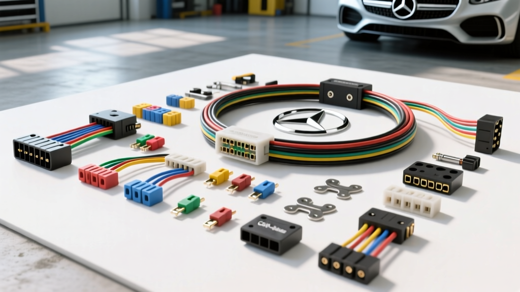
The Hidden Dangers of Mercedes Benz Wiring Harness Replacement
Replacing a wiring harness in a Mercedes-Benz is not a simple plug-and-play endeavor. Whether you are addressing the infamous biodegradable "eco-harness" degradation in 1990s models or routing modern CAN-bus networks in a W212 or W222, the electrical architecture demands surgical precision. A single misplaced pin, an improper splice, or a failure to observe pyrotechnic safety protocols can result in catastrophic ECU failure, uncommanded throttle actuation, or severe electrical fires. This guide outlines the critical safety warnings, common fatal mistakes, and exact technical specifications required for a safe Mercedes Benz wiring harness replacement.
Critical Pre-Work Safety Protocols
Before unclipping a single connector, you must neutralize the vehicle's high-current and pyrotechnic systems. Mercedes-Benz vehicles utilize explosive pyrotechnic fuses in the SRS (Supplemental Restraint System) and high-voltage battery disconnect circuits.
- Battery Disconnect & Wait Time: Disconnect the negative terminal at the main battery (G1/1) and the auxiliary battery if equipped. You must wait a minimum of 15 minutes before touching any SRS components or airbag control units (N2/10). This allows the backup capacitors in the SRS module to fully discharge.
- Pyrotechnic Fuse Handling: On models like the W211 and W219, the rear SAM (Signal Acquisition Module) contains a pyrotechnic battery disconnect. Never probe these circuits with a multimeter while connected; the internal resistance of the meter can trigger the explosive charge.
- Static Discharge (ESD): Modern Mercedes ME-SFI and CDI control units are highly sensitive to ESD. Always wear a grounded wrist strap when handling exposed harness pins or bare ECU connectors.
The Biodegradable Harness Crisis (1992-1996 Models)
If you are performing a Mercedes Benz wiring harness replacement on a W124, W140, or R129 equipped with the M104 or M119 engines, you are likely dealing with the "eco-friendly" biodegradable harness. Mercedes-Benz used a soy-based wire insulation during these years to comply with European environmental regulations. Over time, engine bay heat causes this insulation to turn brittle, flake off, and expose bare copper.
The Electronic Throttle Actuator (ETA) Danger
The most dangerous failure point is the internal wiring of the ETA. The wires inside the throttle body use the same biodegradable insulation. When they short against the metal housing, the ECU receives erratic throttle position sensor (TPS) signals. This can result in severe idle surging, stalling, or uncommanded acceleration. Never attempt to splice or repair the internal ETA wires. The entire ETA unit or a specialized internal harness kit must be installed. Furthermore, the external 14-pin MAS (Motor Protection) connector and the 38-pin X11/4 diagnostic connector are notorious for insulation rot. When replacing the main engine harness, ensure the replacement kit uses modern cross-linked polyethylene (XLPE) or Tefzel insulation rated for 150°C.
Fatal Mistakes & Corrections Matrix
Below is a decision matrix detailing the most common errors technicians and DIYers make during harness replacement, and the engineered corrections required.
| Fatal Mistake | Consequence | Engineered Correction |
|---|---|---|
| Pulling connectors by the wires | Backs out crimp terminals inside the housing, causing intermittent open circuits under vibration. | Always depress the primary and secondary locking tangs. Pull strictly from the hard plastic connector housing. |
| Splicing CAN-bus wires with butt connectors | Alters the 120-ohm characteristic impedance, causing signal reflection and CAN-C network shutdown (limp mode). | Use ultrasonic welding or Raychem SolderSleeve shielded terminations. Maintain the twisted pair geometry. |
| Reusing oxidized ground ring terminals | Creates high-resistance voltage drops, confusing the ME-SFI ECU and triggering phantom O2 sensor codes. | Cut off old ring terminals, crimp new tin-plated copper terminals, and apply dielectric grease before torquing. |
| Routing harness against exhaust manifolds | Radiant heat melts standard PVC loom within 50 hours of operation, causing dead shorts. | Use fiberglass-silicone sleeving (rated to 500°C) and maintain a minimum 4-inch clearance from cast iron exhaust components. |
| Forcing misaligned ECU pins | Bends the male pins on the ME-SFI or TCM, destroying the $2,000+ control module. | Inspect all female cavities with a dental pick before mating. Ensure the connector guide ribs align perfectly before applying pressure. |
Modern CAN-Bus Harness Replacement Protocols
For newer Mercedes-Benz platforms (W204, W212, W222), the wiring harness is less about carrying high current and more about managing high-speed data networks. The physical layer of the CAN-bus must strictly adhere to SAE International J1939 and Bosch physical layer specifications.
Twisted Pair and Impedance Rules
CAN-C (Powertrain) and CAN-B (Interior/Comfort) networks rely on differential signaling. If you are fabricating or repairing a section of the harness, you must maintain the twisted pair. According to Bosch Mobility Solutions CAN-bus physical layer guidelines, the wires must be twisted at a rate of approximately one twist per inch (25mm). Untwisting the wires for more than 50mm (2 inches) to route them through a firewall grommet will introduce electromagnetic interference (EMI) from the alternator and ignition coils, corrupting the data frames.
Wire Gauge and Color Coding
- CAN-H (High): Typically 0.5 mm² (20 AWG). Colors: Orange/Black (CAN-C) or Orange/Red (CAN-B).
- CAN-L (Low): Typically 0.5 mm² (20 AWG). Colors: Orange/Brown or Orange/Blue.
- Termination Resistors: The CAN-C bus requires exactly two 120-ohm termination resistors located at the extreme ends of the network (usually integrated into the ECU and the TCM). Never add aftermarket resistors in parallel, as dropping the resistance below 60 ohms will prevent the CAN transceivers from driving the bus.
Ground Point Torque Specifications
A new wiring harness is only as good as its ground connections. Mercedes-Benz utilizes specific ground studs (designated as W11, W15, etc.) bolted to the chassis or engine block. Paint, powder coating, or corrosion at these points will cause cascading electrical failures. Always clean the mating surface to bare metal using a brass wire brush, apply a thin layer of conductive anti-corrosion compound, and torque to the exact factory specification.
| Fastener Size | Application Example | Torque Specification |
|---|---|---|
| M6 Bolt / Stud | ECU Ground (W11), Sensor Grounds | 9 Nm (80 lb-in) |
| M8 Bolt / Stud | Main Engine Block Ground, Starter Ground | 20 Nm (15 lb-ft) |
| M10 Bolt | Heavy Duty Alternator / Battery Positive Junction | 40 Nm (30 lb-ft) |
Step-by-Step Safe Extraction and Routing
- Document and Photograph: Before disassembly, photograph every connector, ground ring, and routing clip. Mercedes harnesses often feature identical 4-pin connectors for the MAF sensor and the camshaft position sensor; routing them incorrectly will prevent the engine from starting.
- Unclip from the Rear Forward: Always start disconnecting at the ECU and firewall bulkhead, working your way forward to the sensors. This prevents the harness from snagging on the intake manifold runners.
- Transfer Hardware: OEM replacement harnesses rarely come with the hard plastic retaining clips, rubber grommets, or convoluted loom. Carefully cut the zip-ties on the old harness and transfer all Mercedes-specific retaining hardware to the new harness.
- Apply Dielectric Grease: Apply a small amount of silicone dielectric grease to the weather-pack seals of all exterior connectors (e.g., ABS wheel speed sensors, O2 sensors) to prevent moisture ingress and galvanic corrosion.
- Verify Pin Tension: Before plugging into the ECU, use a pin drag tester on a sample of female terminals. If the terminal slides over the male ECU pin with zero resistance, the harness is defective and must be returned.
Conclusion
A Mercedes Benz wiring harness replacement requires a methodical, safety-first approach. By respecting the pyrotechnic wait times, refusing to compromise on CAN-bus twisted pair geometry, and replacing degraded biodegradable insulation with modern XLPE equivalents, you ensure the vehicle's electrical nervous system operates flawlessly. Never cut corners on termination or grounding; the sophisticated control modules in these vehicles will immediately detect the voltage anomalies and default to fail-safe modes.