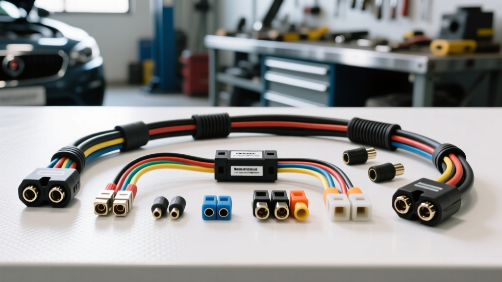
Initial Diagnostic Philosophy for Painless Performance Harnesses
Despite the brand name, installing a Painless Performance wiring harness requires meticulous attention to detail. Whether you are working with a 21-circuit universal kit (Part #10102) or a direct-fit chassis harness for a classic muscle car, 95% of post-installation electrical faults stem from improper grounding, incorrect terminal crimping, or misrouted switched-power feeds. Troubleshooting these harnesses requires abandoning the 'test light' mentality and adopting a systematic, digital multimeter (DMM) voltage-drop methodology. This guide provides a step-by-step troubleshooting flow to isolate and repair faults in Painless Performance systems.
Phase 1: Main Power Feed and Ground Bus Verification
Before chasing individual circuit faults, you must verify the foundation of the harness. Painless Performance kits rely on a centralized power distribution block and a dedicated ground bus. If the main feeds are compromised, downstream diagnostics will yield false positives.
Step 1: Inspect the Main Battery Feed
The main power feed in most Painless kits utilizes a 4 AWG or 1/0 AWG primary cable routed from the battery positive terminal to the main power distribution block, protected by a 100A to 150A MegaFuse or ANL fuse.
- Test Point A: Battery positive post.
- Test Point B: Main distribution block input stud.
- Acceptable Voltage Drop: Less than 0.10V with the engine cranking.
If your DMM reads a voltage drop greater than 0.10V, inspect the heavy-gauge ring terminals. Painless specifies that all heavy-gauge lugs must be crimped with a hex-crimp die or soldered, then sealed with adhesive-lined heat shrink to prevent galvanic corrosion.
Step 2: Validate the Central Ground Bus
A common failure mode in aftermarket harnesses is 'floating grounds,' where accessories seek a path to ground through other circuits (backfeeding). Painless kits include a centralized copper ground bus bar. Ensure the main ground strap connecting the bus bar to the engine block or chassis is at least 8 AWG (preferably 4 AWG) and is bolted to bare, unpainted metal. Use a star washer to bite through surface rust or powder coat.
Phase 2: Symptom-Specific Troubleshooting Flows
Symptom A: Complete No-Crank / No-Start Condition
If the ignition key is turned to 'Start' and the starter solenoid does not engage, the fault lies in the starter control circuit. In Painless harnesses, this circuit is typically a 12 AWG Yellow wire.
- Verify Ignition Switch Output: Probe the 'ST' (Start) terminal on the back of the ignition switch. With the key held in the crank position, you should read full battery voltage (12.2V - 12.6V). If 0V, the ignition switch is faulty or the main 10 AWG Red 'BAT' feed to the switch is open.
- Trace the Neutral Safety Switch (NSS): The Yellow wire routes through the NSS (or clutch safety switch). Probe the input side of the NSS. If 12V is present, probe the output side while cranking. If 0V on the output, the NSS is misadjusted or failed.
- Starter Solenoid 'S' Terminal Check: Follow the Yellow wire to the starter solenoid 'S' terminal. If you have 10.5V+ at the 'S' terminal during crank but the starter does not engage, the wiring harness is intact, and the starter solenoid or starter motor is defective.
Symptom B: Intermittent Headlight or Accessory Failure
Headlights drawing excessive current through aging switches cause voltage drops and melted connectors. Painless harnesses mitigate this by using relays, but faults still occur.
- Identify the Circuit: Headlight low beams are typically routed via a 10 AWG Brown wire, while high beams use a 10 AWG Tan wire. These are protected by 20A or 25A fuses in the central block.
- Perform a Loaded Voltage Drop Test: Turn the headlights on. Place the DMM's red lead on the fuse output and the black lead on the headlight bulb's positive pin. A reading above 0.5V indicates excessive resistance in the wire or a failing Weather-Pack connector.
- Inspect Weather-Pack Terminals: Painless uses Delphi Weather-Pack connectors for exterior lighting. If the male and female terminals lack the audible 'click' upon insertion, the secondary lock (TPA - Terminal Position Assurance) is missing, or the terminal tangs are crushed, leading to micro-arcing and intermittent failure.
Symptom C: Alternator Overcharge or Undercharge
When integrating a GM CS130 or 1-Wire alternator with a Painless harness, the exciter and sense wires are frequently misrouted.
- Main Charge Wire: Must be 10 AWG Red, routed directly from the alternator BAT post to the main distribution block or battery positive. Never route this through a standard fuse; use a fusible link or MegaFuse.
- Exciter Wire (Terminal L): Painless provides an 18 AWG Red/White wire. This must be connected to an ignition-switched 12V source (Pink wire circuit) with a 565-ohm inline resistor or a 12V warning bulb. If connected to constant 12V, the alternator will drain the battery when the vehicle is parked.
- Sense Wire (Terminal S): The 16 AWG Red sense wire must read true battery voltage. Route it directly to the battery positive terminal or the main distribution block stud, not the alternator BAT post, to ensure the regulator compensates for voltage drop across the main charge cable.
Painless Performance Circuit Color Code & AWG Reference
Use the following reference table to quickly identify standard wire functions and gauges in universal Painless Performance chassis harnesses. Always cross-reference with the specific manual for your part number, as direct-fit harnesses may vary.
| Circuit Function | Wire Color | AWG Size | Standard Fuse Rating | Connector Type |
|---|---|---|---|---|
| Main Battery Feed | Red | 4 AWG / 1/0 | 100A - 150A Mega | Heavy Ring Terminal |
| Ignition Switch (BAT) | Red | 10 AWG | 30A Maxi | Ring / Spade |
| Ignition Switched (RUN) | Pink | 12 AWG | 15A - 20A | Weather-Pack / Bulkhead |
| Starter Solenoid (Start) | Yellow | 12 AWG | Unfused (Cranking) | Push-On Spade |
| Headlights (Low Beam) | Brown | 10 AWG | 20A | Weather-Pack |
| Headlights (High Beam) | Tan | 10 AWG | 20A | Weather-Pack |
| Wiper Motor | Blue | 12 AWG | 15A | Metri-Pack 150 |
| Instrument Gauges | Pink / Gray | 14 AWG | 5A - 10A | Metri-Pack 150 |
Advanced Diagnostic Tools and Crimping Standards
When repairing a damaged section of a Painless harness, the integrity of the repair is paramount. According to SAE J1128 standards for low-tension automotive cables, solder alone is prohibited for high-vibration harness repairs due to the creation of a brittle stress riser at the edge of the solder joint. You must use open-barrel crimp terminals with a ratcheting crimp tool designed for Weather-Pack or Metri-Pack terminals. The crimp should exhibit a distinct 'bell mouth' at the wire entry to prevent the sharp edge of the terminal from shearing copper strands.
For diagnosing complex parasitic draws or CAN-bus integration faults on modern LS-swapped vehicles utilizing a Painless engine swap harness, a digital storage oscilloscope (DSO) is required. As noted in Fluke's automotive electrical troubleshooting guidelines, standard DMMs average voltage over time and will miss micro-second dropouts in digital sensor signals (like crankshaft position sensors) routed through the engine harness bulkhead connector.
Final Verification Protocol
After executing repairs, perform a 'wiggle test' with the engine running and all accessories loaded (headlights, A/C blower on high, wipers active). Monitor the main distribution block voltage. It should remain above 13.8V. Finally, apply dielectric grease (specifically NYE 812A or equivalent) to all Weather-Pack and Metri-Pack connectors to prevent moisture ingress and fretting corrosion, ensuring your Painless Performance wiring harness remains reliable for years to come. For specific pin-out diagrams and bulkhead routing instructions, always consult the official Painless Performance manual index corresponding to your exact kit part number.