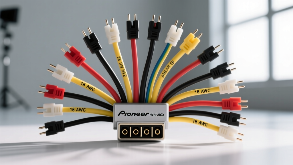
Introduction to the Pioneer MVH-200EX Electrical Architecture
The Pioneer MVH-200EX is a highly popular digital media receiver designed for shallow-depth installations. Because it lacks an internal CD mechanism, its physical footprint is compact, but its electrical architecture relies on the industry-standard Pioneer 16-pin ISO-style TSO harness. Understanding the precise pinout, wire gauge (AWG) requirements, and integration protocols for the Pioneer MVH-200EX wiring harness is critical for achieving a noise-free, reliable installation. This technical specification reference details the exact wire color codes, current capacities, and vehicle adapter integration strategies required by professional installers.
16-Pin ISO Harness Pinout and Wire Color Specifications
The primary power and speaker connections for the MVH-200EX are routed through a single 16-pin Molex-style connector. Below is the definitive pinout chart based on Pioneer's official installation documentation and standard aftermarket automotive electrical practices.
| Pin | Wire Color | Function | AWG | Technical Notes |
|---|---|---|---|---|
| 1 | Yellow | Battery (+) Constant 12V | 18 | Memory and preset retention. Must be fused (10A). |
| 2 | Red | Ignition (+) Switched 12V | 18 | Triggers head unit power state. Connect to ACC circuit. |
| 3 | Black | Chassis Ground (-) | 18 | Must terminate to bare, unpainted chassis metal. |
| 4 | Blue/White | System Remote Control | 18 | Amp turn-on. Max output 300mA. Use relay for high draw. |
| 5 | Orange/White | Illumination / Dimmer | 18 | Triggers display dimming. Requires 12V+ analog signal. |
| 6 | White | Front Left Speaker (+) | 18 | Do not ground to chassis. |
| 7 | White/Black | Front Left Speaker (-) | 18 | Floating ground output. |
| 8 | Gray | Front Right Speaker (+) | 18 | Do not ground to chassis. |
| 9 | Gray/Black | Front Right Speaker (-) | 18 | Floating ground output. |
| 10 | Green | Rear Left Speaker (+) | 18 | Do not ground to chassis. |
| 11 | Green/Black | Rear Left Speaker (-) | 18 | Floating ground output. |
| 12 | Purple | Rear Right Speaker (+) | 18 | Do not ground to chassis. |
| 13 | Purple/Black | Rear Right Speaker (-) | 18 | Floating ground output. |
| 14 | Light Green | Mute Control | 18 | Ground to mute. Rarely used in modern installs. |
| 15 | N/C | Not Connected | - | Reserved / Empty pin. |
| 16 | N/C | Not Connected | - | Reserved / Empty pin. |
Wire Gauge (AWG), Fusing, and Current Capacity
The Pioneer MVH-200EX harness utilizes 18 AWG stranded copper wire for both power and speaker leads. According to SAE J1128 standards for low-tension primary cables, 18 AWG wire is sufficient for the head unit's internal 10A fuse limit and its built-in MOSFET amplifier, which produces 14 watts RMS x 4 channels (50W peak x 4).
Power Extension Rules
If the factory harness adapter does not reach the vehicle's power distribution block or chassis ground point, you must extend the Yellow, Red, and Black wires. When extending, never drop below 18 AWG. For runs exceeding 6 feet, step up to 16 AWG or 14 AWG to prevent voltage drop, which can cause the MVH-200EX to reboot during heavy bass transients when the internal amplifier draws maximum current. Always install an inline 10A ATO/ATC blade fuse on the Yellow constant 12V wire within 6 inches of the power source.
Speaker Wire Limitations
The internal amplifier's speaker outputs are BTL (Bridge-Tied Load). The negative speaker wires (White/Black, Gray/Black, etc.) carry an active signal and are not true grounds. Grounding any of these 18 AWG speaker wires to the vehicle chassis will instantly destroy the Pioneer's internal amplifier IC. If you are bypassing the internal amp to run 4-channel RCA preouts to an external DSP or amplifier, the 18 AWG speaker wires on the harness remain unused and must be individually heat-shrunk and taped back.
Steering Wheel Control (SWC) and Auxiliary Pigtails
A common point of confusion for installers referencing the Pioneer MVH-200EX wiring harness is the absence of Steering Wheel Control (SWC) wires on the main 16-pin block. The MVH-200EX utilizes a dedicated, separate 3.5mm female auxiliary jack on the rear chassis for SWC integration.
- Standard Analog SWC: Vehicles with analog resistive ladder steering wheel buttons (common in older Toyota, Honda, and Hyundai models) require a 3.5mm-to-bare-wire adapter (like the Axxess ASWC-1 or PAC SWI-JACK). You will splice the vehicle's SWC wire directly to the adapter, not the Pioneer harness.
- CAN-Bus Data SWC: For modern vehicles utilizing CAN-bus or GMLAN data networks for steering wheel buttons, a data interface module (such as the iDatalink Maestro or PAC RP5-CH11) is required. These modules translate the digital network data into analog resistive signals that the MVH-200EX's 3.5mm port can understand.
Vehicle-Specific Harness Adapter Integration
To install the MVH-200EX without cutting the factory wiring, you must mate the Pioneer 16-pin harness to a vehicle-specific adapter. Based on the Crutchfield Vehicle Fit Database, common pairings include:
- Ford / Lincoln / Mazda (1998-2015): Metra 70-1771 or 70-5520. Note that the Orange/White illumination wire on the Pioneer harness may not have a corresponding wire on the Ford adapter, as Ford often uses a CAN-bus dimming signal. You may need to leave the Orange/White wire disconnected or use a 12V dimmer simulator.
- General Motors (1995-2012 Non-Class 2 Data): Metra 70-1858. The Pioneer Red (ACC) wire will connect to the adapter's Yellow wire, and the Pioneer Yellow (Constant) will connect to the adapter's Orange wire. Always verify with a multimeter; GM wire colors frequently invert standard EIA color codes.
The Illumination Wire Dilemma (Orange/White)
The Orange/White wire on the Pioneer MVH-200EX harness expects a positive 12V trigger when the headlights are turned on to dim the display. In vehicles from 2010 and newer, the factory lighting circuit is often multiplexed, PWM (Pulse Width Modulated), or controlled via CAN-bus, meaning there is no standard 12V analog illumination wire. Connecting a PWM lighting wire to the Pioneer's Orange/White wire will cause the head unit display to flicker violently or trigger a 'Check Vehicle' warning on the dash. In these applications, leave the Orange/White wire isolated and set the MVH-200EX internal dimmer settings to 'Auto' or manual override.
Diagnostic Troubleshooting Decision Tree
When diagnosing electrical faults related to the Pioneer MVH-200EX wiring harness, follow this systematic decision tree to isolate the failure mode.
Symptom: Head Unit Loses Radio Presets and Clock Settings
- Step 1: Turn off the ignition and remove the key. Does the unit power down completely?
- If Yes: The Red (Switched) and Yellow (Constant) wires are swapped at the adapter. The unit is losing all power when the key is off. Swap the Red and Yellow wire connections.
- If No (Unit stays on or goes to standby but loses memory): Proceed to Step 2.
- Step 2: Check the inline fuse on the Yellow wire. Is it blown?
- If Yes: Replace with a 10A fuse. Check for pinched wires behind the DIN sleeve.
- If No: Use a multimeter to test the Yellow wire at the back of the radio. It must read a steady 12.0V - 12.6V at all times. If voltage drops to 0V when the key is off, trace the Yellow wire back to the vehicle's constant 12V source (e.g., battery or always-hot fuse panel slot).
Symptom: Alternator Whine in the Speakers
- Step 1: Does the pitch of the whine change with engine RPM?
- If Yes: You have a ground loop. The Black (Ground) wire on the Pioneer harness is likely grounded to a painted surface, a seatbelt bolt, or shared with a high-current accessory. Relocate the Black wire ground to a dedicated, sanded bare-metal point on the chassis using a ring terminal.
- If No (Static or popping only): Check for loose crimp connections on the RCA preouts or speaker wire adapters. Ensure no speaker negative wires are touching the chassis.
Symptom: External Amplifier Does Not Turn On
- Step 1: Test the Blue/White (Remote Turn-On) wire with a multimeter while the MVH-200EX is powered on.
- If 0V: The internal switching transistor on the Pioneer PCB may be blown due to exceeding the 300mA limit. You will need to install a relay triggered by the Red (ACC) wire to send a dedicated 12V remote signal to the amplifier.
- If 12V is present at the radio but 0V at the amp: The 18 AWG Blue/White wire is broken or disconnected somewhere in the harness extension run.
Expert Installation Best Practices
For a professional-grade installation of the Pioneer MVH-200EX wiring harness, abandon the use of cheap twist-on crimp caps. The optimal connection method is the 'Military Splice' (Western Union splice) followed by rosin-core soldering and adhesive-lined dual-wall heat shrink tubing. This prevents oxidation, ensures maximum current transfer, and completely eliminates the risk of a wire pulling loose from the vibrations inherent in automotive environments. Always use a plastic trim removal tool to route the harness adapter behind the dash, ensuring the wires are not pinched between the metal DIN sleeve and the plastic dashboard sub-structure.