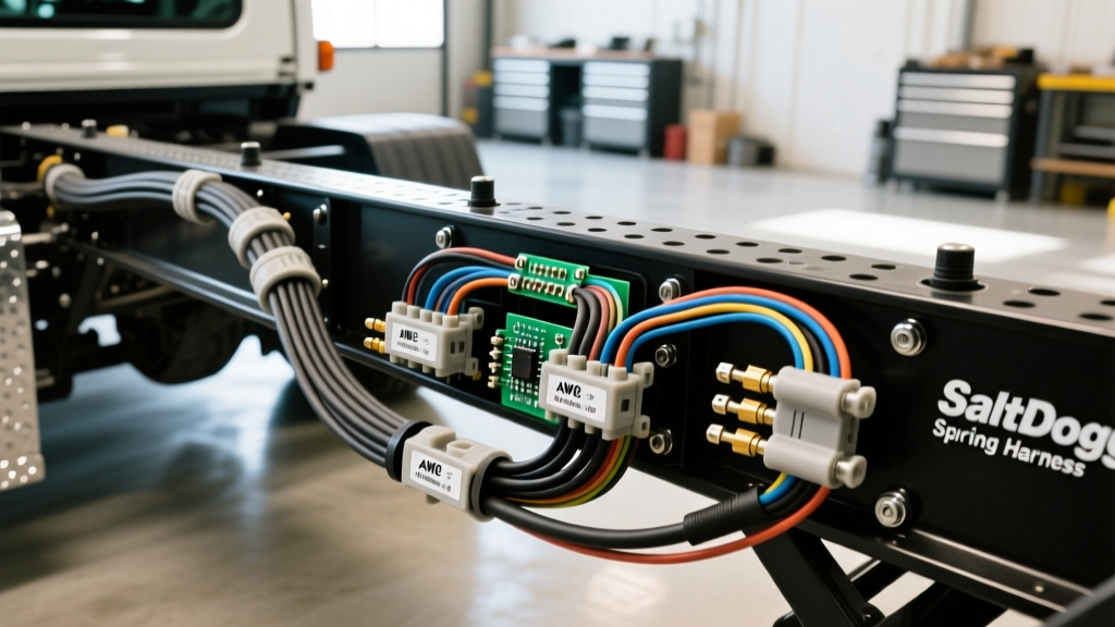
The Case for a Custom Harness Upgrade
When outfitting a modern work truck—such as a Ford F-350 or Ram 3500—for municipal snow and ice control, the OEM wiring harness provided with your spreader is often the weakest link. Factory SaltDogg spreader wiring harness kits are designed for standard bed lengths and general use. However, when you are running an extended wheelbase, routing through complex upfitter compartments, or operating in extreme sub-zero temperatures, the factory harness can suffer from severe voltage drop, brittle insulation, and connector failure.
Upgrading to a custom-fabricated, heavy-duty harness ensures that your SaltDogg PRO or MDS series spreader receives the massive current required to keep the auger and spinner motors operating at peak torque. This guide covers the complete electrical architecture, wire gauge specifications, and connector pinouts required to build a professional-grade spreader harness from scratch.
Power Circuit Architecture and AWG Requirements
The primary failure mode in spreader electrical systems is voltage drop across the main power feed. SaltDogg high-torque 12V DC motors can draw upwards of 180 amps under peak stall conditions (such as when breaking up a frozen salt bridge in the hopper). If the wire gauge is too small, the voltage reaching the motor drops below 11V, resulting in sluggish operation, overheated windings, and tripped thermal breakers.
According to the SAE J1128 Low Tension Primary Cable Standard, automotive wire must be sized not just for continuous amperage, but for voltage drop over the total circuit length (positive and negative). For a typical crew-cab truck with an 8-foot bed, the total round-trip wire length from the battery to the spreader solenoid and back to the chassis ground can exceed 25 feet.
Main Power Specification Table
| Circuit Function | AWG Size | Wire Color | Insulation Type | Max Continuous Amps |
|---|---|---|---|---|
| Battery to Main Solenoid (Contactor) | 1/0 AWG | Red | SGX (Cross-linked) | 190A |
| Main Solenoid to Motor Harness Split | 2 AWG | Red | SGX (Cross-linked) | 130A |
| Motor Ground Return to Chassis | 1/0 AWG | Black | SGX (Cross-linked) | 190A |
| Controller Main Power Feed | 10 AWG | Red | TXL | 30A |
Note: Always use SAE J1128 SGX (cross-linked polyethylene) insulation for under-hood and under-chassis routing. SGX withstands higher temperatures and resists abrasion from road debris far better than standard PVC-insulated GXL or THHN wire.
Control Circuit and PWM Signal Integrity
Modern SaltDogg controllers utilize Pulse Width Modulation (PWM) to dictate spinner speed, allowing for precise material application rates (e.g., 200 lbs per lane mile). The PWM signal operates by rapidly switching the 12V DC power on and off, typically at a frequency between 200Hz and 400Hz.
Because the spreader motors generate massive amounts of Electromagnetic Interference (EMI) and back-EMF during operation, running unshielded control wires parallel to the 1/0 AWG motor feeds will induce noise into the PWM signal. This causes the controller to misread the spinner speed, resulting in erratic material spreading. To prevent this, all control and CAN bus data wires must be routed in a separate loom or utilize shielded twisted-pair (STP) cable, with the shield drain wire grounded at the controller end only.
12-Pin Circular Connector Pinout Chart
To connect the truck-side harness to the spreader-side harness, heavy-duty circular connectors are mandatory. While older setups used molded 7-pin plastics that crack at -10°F, professional upfitters utilize the TE Connectivity Deutsch HD30 Series or equivalent AMP CPC metal-shell connectors. Below is the standard 12-pin configuration for a dual-motor SaltDogg PRO series setup.
| Pin # | Function | Wire Color | AWG | Contact Size |
|---|---|---|---|---|
| 1 | Main Solenoid Trigger (12V+ from Cab) | Blue | 12 AWG | Size 16 |
| 2 | Controller Ground | Black | 12 AWG | Size 16 |
| 3 | Spinner PWM Signal | Yellow | 16 AWG (Shielded) | Size 16 |
| 4 | Auger PWM Signal | Green | 16 AWG (Shielded) | Size 16 |
| 5 | Vibrator Solenoid (12V+) | Orange | 14 AWG | Size 16 |
| 6 | Beacon/Strobe Light Trigger | White | 16 AWG | Size 16 |
| 7 | CAN High / Data + | Purple | 18 AWG (STP) | Size 20 |
| 8 | CAN Low / Data - | Gray | 18 AWG (STP) | Size 20 |
Pins 9-12 are typically reserved for auxiliary functions or future firmware expansions and should be capped with blanking plugs to maintain the IP68 weatherproof seal of the connector housing.
Step-by-Step Harness Fabrication and Routing
Step 1: Termination and Weatherproofing
When terminating the 1/0 AWG and 2 AWG battery cables, use closed-barrel, adhesive-lined copper lugs (such as 3M MDT or Ancor Marine grade). The adhesive lining is non-negotiable for winter service vehicles. When heated, the polyolefin adhesive melts and seals the wire strands, preventing salt water from traveling up the wire via capillary action—a phenomenon that causes green corrosion to bloom inside the connector months after installation.
Step 2: Cab Pass-Through Integration
Do not drill new holes through the firewall or cab floor if avoidable. Modern trucks like the Ford Super Duty feature dedicated upfitter pass-through grommets located behind the driver-side kick panel or under the driver-side door sill. Route the 12-pin circular connector through this grommet. If the connector backshell is too large, you must fabricate a secondary watertight bulkhead connector using Deutsch DT series connectors on the interior side of the cab.
Step 3: Loom and Abrasion Protection
Wrap the exterior harness in split braided nylon sleeving, followed by a layer of Tesa 51036 PET cloth tape. This combination provides exceptional abrasion resistance against vibrating truck beds and prevents the harness from emitting rattling noises against the chassis. Secure the harness every 12 inches using UV-resistant zip ties with stainless steel mounting pads; never use standard nylon ties that will shatter in freezing temperatures.
Integrating with Modern Truck Upfitter Switches
Most modern work trucks come equipped with auxiliary upfitter switches (e.g., Ford's AUX1-AUX6). You can wire the SaltDogg main solenoid trigger (Pin 1) directly to an upfitter switch, provided the switch is rated for the solenoid coil's inrush current. A standard heavy-duty Trombetta contactor coil draws approximately 6 to 8 amps. If your truck's upfitter switch is rated for 10A or higher, a direct connection is safe. If the switch is rated lower, or if you are adding a secondary master kill-switch, you must use a 30A Bosch-style relay to isolate the cab switch from the spreader solenoid coil.
Diagnostics and Voltage Drop Testing
After installation, perform a live voltage drop test before loading the hopper with salt. With the spreader motors running under load (you can simulate this by applying a mechanical brake to the spinner), use a digital multimeter to measure the voltage between the battery positive post and the motor positive terminal. According to Buyers Products SaltDogg Installation Manuals, a voltage drop exceeding 0.5V on the positive side or 0.2V on the ground side indicates excessive resistance. High resistance is almost always caused by an under-crimped lug, a corroded chassis ground point, or an undersized wire gauge.
By upgrading your SaltDogg spreader wiring harness with proper SGX cabling, shielded PWM lines, and metal-shell circular connectors, you eliminate the most common electrical failure points in snow and ice control operations, ensuring your equipment runs reliably through the harshest winter storms.