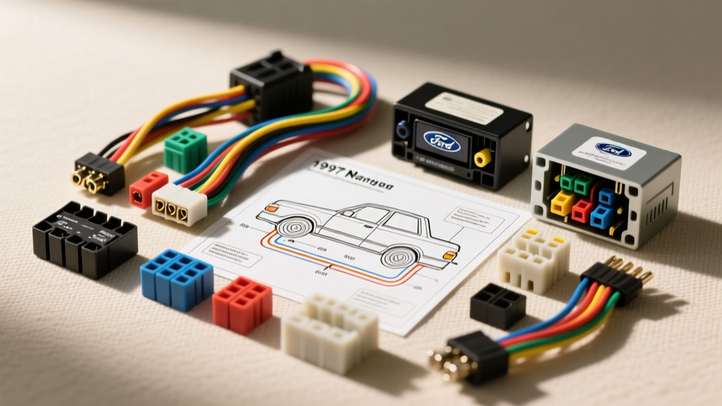
Introduction to the 1997 Ford Ranger Audio Electrical Architecture
The 1997 Ford Ranger remains a cornerstone of the compact truck segment, but upgrading its aging audio system requires a thorough understanding of its specific electrical architecture. Unlike modern vehicles that rely heavily on CAN-bus data networks for accessory control, the 1997 Ranger utilizes a traditional analog switched-power system governed by the Generic Electronic Module (GEM) and a series of mechanical relays. While this analog layout is generally forgiving for DIY car audio enthusiasts, the 25-plus-year-old wiring harnesses are brittle, and the factory circuits were never designed to handle the high-current demands of modern aftermarket head units and amplifiers. Relying solely on a generic 1997 Ford Ranger stereo wiring diagram without understanding the underlying safety protocols and common failure modes is a fast track to blown fuses, parasitic battery draws, or catastrophic module failure.
Critical Safety Protocols Before Disconnecting the Battery
Before cutting, splicing, or probing any wire behind the dash, you must address the vehicle's Supplemental Restraint System (SRS). The 1997 Ranger is equipped with a Restraints Control Module (RCM) and dual front airbags. The RCM contains high-voltage capacitors that can retain enough charge to deploy an airbag even after the battery is disconnected.
- Disconnect the Negative Terminal: Use a 10mm socket to remove the negative battery cable. Isolate it from the battery post to prevent accidental contact.
- Wait 15 Minutes: According to Ford Motorcraft Service Documentation, you must wait a minimum of 15 minutes for the RCM backup power supply to deplete before working near the steering column or lower dash panel.
- Capacitor Discharge on Audio Equipment: If you are removing an existing aftermarket amplifier, ensure you wait at least 5 minutes for the amp's internal capacitors to discharge before touching the power or ground terminals to avoid severe DC arcing.
The 1997 Ford Ranger Stereo Wiring Diagram: OEM vs. Aftermarket
The 1997 Ranger typically utilizes a standard Ford 16-pin radio connector (or a dual 8-pin setup depending on the exact build month and trim level). When integrating an aftermarket head unit, it is highly recommended to use a Metra 70-1771 or Scosche F02B wiring harness adapter. This prevents cutting the OEM harness and preserves the vehicle's resale value. Below is the definitive pinout and color code reference for the standard 1997 Ranger audio circuit.
| Function | OEM Factory Wire Color | EIA/CTA Aftermarket Color | OEM Pin (16-Pin) |
|---|---|---|---|
| Constant 12V+ (Memory) | Green/Yellow | Yellow | Pin 1 |
| Switched 12V+ (Ignition) | Yellow/Black | Red | Pin 2 |
| Chassis Ground | Black/Light Green | Black | Pin 3 |
| Illumination | Light Blue/Red | Orange/White | Pin 4 |
| Dimmer | Orange/Black | Orange | Pin 5 |
| Left Front Speaker (+/-) | Orange/Light Green & Orange/Black | White & White/Black | Pins 6, 7 |
| Right Front Speaker (+/-) | White/Light Green & White/Black | Gray & Gray/Black | Pins 8, 9 |
| Left Rear Speaker (+/-) | Pink/Light Green & Pink/Black | Green & Green/Black | Pins 10, 11 |
| Right Rear Speaker (+/-) | Brown/White & Brown/Black | Purple & Purple/Black | Pins 12, 13 |
Note: Always verify wire functions with a digital multimeter (DMM) before making permanent connections. Previous owners may have altered the harness.
Top 4 Installation Mistakes That Destroy Ranger Electrical Systems
Even with the correct 1997 Ford Ranger stereo wiring diagram in hand, installers frequently make critical errors that compromise the truck's electrical integrity. Avoid these four common pitfalls at all costs.
Mistake 1: Shorting the Illumination Circuit and Frying the GEM Module
The Light Blue/Red illumination wire on the Ranger's harness is tied directly to the headlight switch and the Generic Electronic Module (GEM). The GEM controls vital functions including the windshield wipers, interior dome lights, and battery saver relays. A common mistake is letting the bare end of the aftermarket Orange/White illumination wire touch the metal dash frame during installation. This creates a dead short to ground, instantly blowing the 15A instrument panel fuse. Worse, if the short occurs while the circuit is energized, the voltage spike can backfeed and permanently fry the GEM module's internal logic board. Fix: Always use heat-shrink butt connectors or solder-and-shrink methods for the illumination wire. Never use cheap twist-on wire nuts or exposed electrical tape.
Mistake 2: Grounding to the Steering Column or Painted Dash Frame
The factory ground wire (Black/Light Green) must handle the return current for the head unit, which can easily exceed 10 amps on modern decks with built-in 50Wx4 amplifiers. Many installers lazily wrap the ground wire around a bolt on the steering column or a painted bracket under the dash. The steering column is isolated by rubber bushings and bonded only by a thin grounding strap, which is insufficient for audio return currents. This results in alternator whine, voltage drops, and head unit reboots during heavy bass transients. Fix: Route a dedicated 14 AWG or 12 AWG ground wire to the main steel dash crossmember. Sand the contact area down to bare, shiny metal, attach an 8mm ring terminal, and torque the bolt to 12 ft-lbs. Apply a dab of dielectric grease over the terminal to prevent galvanic corrosion.
Mistake 3: Ignoring the Premium Sound Amplifier Bypass
If your 1997 Ranger is equipped with the factory premium cassette/CD system, it utilizes an external 4-channel amplifier (usually mounted under the passenger seat or behind the right kick panel). The wiring from the factory head unit to this amp carries low-level pre-out signals, not high-level speaker outputs. If you plug an aftermarket head unit directly into this harness using a standard adapter, you will send 50 watts of high-level amplified signal into the factory amplifier's low-level inputs. This will cause massive clipping, severe distortion, and will likely blow the factory speakers and the amp's input stage. Fix: You must either bypass the factory amplifier entirely and run new 16 AWG speaker wire directly from the dash to the door speakers, or use a specialized line-out converter (LOC) to step the aftermarket deck's high-level outputs down to RCA pre-outs.
Mistake 4: Overloading the Accessory Delay Relay Circuit
Fords of this era feature an 'Accessory Delay' circuit, allowing the radio and power windows to function for up to 10 minutes after the key is removed, until the driver's door is opened. Tying aftermarket accessories (like LED halo rings or radar detectors) into the radio's switched 12V+ (Yellow/Black) wire can overload the accessory delay relay. If the combined draw exceeds the relay's 10A rating, the relay contacts will weld together, causing a parasitic draw that will kill your battery overnight. Fix: Use the head unit's switched 12V wire only as a trigger signal for a secondary 30A automotive relay if you need to power auxiliary accessories.
SAE J1128 Wire Gauge & Crimping Specifications
When upgrading the power delivery for a new head unit or adding an external amplifier, you must adhere to the SAE J1128 Low Voltage Primary Cable Standard. Using undersized wire causes voltage drop, leading to thermal runaway and melted insulation. Below are the strict AWG requirements for the 1997 Ranger's 12V electrical system.
| Application | Minimum Wire Gauge (AWG) | Max Run Length | Terminal / Connection Type |
|---|---|---|---|
| Head Unit Power/Ground | 14 AWG (OEM is 16 AWG) | 6 Feet | Solder & Heat Shrink |
| Amplifier Power (Up to 400W RMS) | 8 AWG OFC Copper | 15 Feet | Set-Screw Ring Terminal |
| Amplifier Power (400W - 800W RMS) | 4 AWG OFC Copper | 15 Feet | Set-Screw Ring Terminal |
| Amplifier Remote Turn-On | 18 AWG | 15 Feet | Crimp Butt Connector |
Warning: Never use Copper-Clad Aluminum (CCA) wire for car audio power runs. CCA has a higher resistance than Oxygen-Free Copper (OFC) and is a leading cause of mobile electronics fires. Always verify the wire cross-section is pure copper.
Post-Installation Troubleshooting: Parasitic Draws
After completing your stereo installation and reconnecting the battery, you must verify that the new equipment is not causing a parasitic draw. The 1997 Ranger's GEM module and factory anti-theft systems typically draw between 20mA and 40mA when the vehicle is fully asleep (which can take up to 20 minutes after closing the doors and turning off the dome lights).
The Testing Procedure:
- Set your Digital Multimeter (DMM) to the 10A DC current setting.
- Disconnect the negative battery terminal.
- Place the DMM in series: connect the red probe to the negative battery cable clamp, and the black probe to the negative battery post.
- Wait 20 minutes for the GEM module to enter sleep mode and the factory radio capacitors to discharge.
- Read the amperage. If the draw is above 50mA (0.05A), you have a parasitic drain.
Common Causes of High Draw Post-Install: The most frequent culprit is an aftermarket head unit that fails to shut down its internal microprocessor due to the Constant 12V and Switched 12V wires being reversed at the harness adapter. If the Yellow and Red wires are swapped, the radio remains in a 'standby' state, drawing 200mA to 500mA continuously, which will drain a standard Group 65 battery in less than 48 hours. Always double-check your pinout against the Consumer Technology Association (CTA) mobile electronics standards before finalizing the dash reassembly.