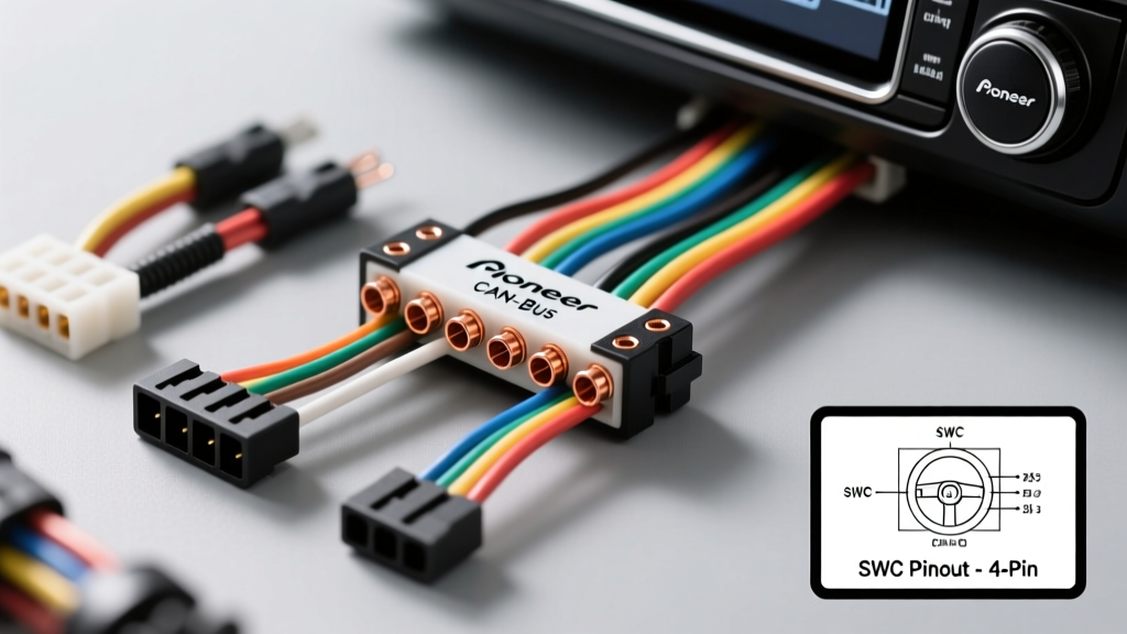
Decoding the Pioneer Head Unit Wiring Diagram: Beyond the Basics
For automotive electrical specialists and advanced car audio integrators, a standard Pioneer head unit wiring diagram is merely the starting point. While basic installations rely on simple color-matching via T-harnesses, true custom integration—especially with Pioneer's flagship NEX (Networked Entertainment eXperience) series—requires a deep understanding of proprietary pinouts, CAN-bus data protocols, and high-current power delivery. This advanced technical deep dive dissects the electrical architecture of modern Pioneer receivers, moving past the rudimentary 16-pin ISO standard to explore 22-pin proprietary blocks, steering wheel control (SWC) resistor ladders, and 5V pre-out signal integrity.
ISO 10487 vs. Pioneer’s Proprietary 22-Pin NEX Harness
The international standard ISO 10487 defines the 16-pin connector block used across most European and Asian vehicles. However, Pioneer’s advanced multimedia receivers, such as the AVIC-W8600NEX or DMH-W2770NEX, utilize a proprietary 22-pin or 18-pin Molex-style connector to accommodate features that the ISO standard cannot support natively. These include dedicated park brake inputs for video bypass, high-voltage RCA pre-out grounds, and digital data lines for HDMI or USB-C routing.
When adapting a Pioneer NEX unit to a factory ISO harness, integrators must map the proprietary pins to the vehicle's CAN-bus or LIN-bus networks. Misinterpreting the illumination circuit is a common failure point. While older units used a simple 12V trigger for dashboard dimming, modern Pioneer units expect a Pulse Width Modulation (PWM) signal or a variable resistance ground to properly scale the LCD backlight. Feeding a static 12V to a PWM-expecting pin can result in blown surface-mount resistors on the head unit's main PCB.
High-Current Power Delivery and AWG Upgrades
A critical oversight in advanced installations is relying on the factory wiring harness for power delivery. The standard Pioneer harness utilizes 18 AWG (approx. 0.82mm²) copper for the Yellow (Constant 12V) and Red (Switched 12V) wires. While sufficient for basic 4x50W MOSFET units, NEX receivers with built-in Class-D amplifiers and large capacitive touchscreens can draw continuous currents exceeding 15A, with transient spikes up to 22A during heavy bass transients.
According to standard automotive electrical practices, 18 AWG wire exhibits significant voltage drop over runs longer than 6 feet. To prevent the head unit from rebooting during high-volume bass notes—a symptom of the internal protection circuit triggering due to undervoltage—advanced installers must bypass the 18 AWG harness wires. We recommend splicing 12 AWG (or ideally 10 AWG) OFC (Oxygen-Free Copper) wire directly to the Yellow and Black terminals at the back of the radio chassis, routing this upgraded pair directly to the vehicle's battery and a dedicated chassis ground point, fused at 25A within 18 inches of the battery terminal.
Advanced Pinout Matrix: Pioneer NEX 22-Pin Connector
Below is the technical reference matrix for the secondary 22-pin proprietary block found on high-end Pioneer NEX multimedia units. This block handles data, advanced triggers, and high-fidelity audio grounds.
| Pin | Wire Color | Function | Technical Specifications & Notes |
|---|---|---|---|
| 1 | Light Green | Park Brake Input | Requires ground to enable video. Must be tied to OEM electronic parking brake relay or bypass module. |
| 2 | Orange/White | Illumination / Dimmer | Accepts PWM or 0-12V analog. Do not connect to LED CAN-bus systems without a PAC/Axxess step-down resistor. |
| 3 | Blue/White | Amp Turn-On / Antenna | Max current output: 300mA. Use a 4-pin automotive relay for multi-amp or cooling fan triggers. |
| 4 | Purple/White | Mute Control | Active Low. Grounding this pin mutes audio for Bluetooth phone calls or OEM chime integration. |
| 5 | Yellow/Black | Steering Wheel Control (SWC) | Analog resistor ladder input. Expect 0V to 3.3V logic. Requires PAC SWI-RC or Axxess ASWC-1 interface. |
| 6 | Black/White | Pre-Out Shield Ground | Isolated ground for RCA outputs. Crucial for preventing alternator whine via common-mode rejection. |
| 7 | White/Red | Reverse Gear Trigger | +12V input. Activates backup camera overlay and mutes audio. Tie to OEM reverse lamp circuit. |
CAN-Bus Integration and Steering Wheel Control (SWC) Logic
Modern vehicles utilize GMLAN, MS-CAN, or HS-CAN networks to transmit steering wheel button presses. The Pioneer head unit cannot natively decode these proprietary digital packets. Therefore, the 'Pioneer head unit wiring diagram' must incorporate a data-bus interface module (such as the PAC RP4-CH11 or Maestro RR). These modules sniff the CAN-bus, translate the digital button press into an analog voltage drop, and feed it to Pin 5 (Yellow/Black) on the Pioneer harness.
When wiring the SWC line, it is imperative to avoid running the analog SWC wire parallel to high-current speaker wires or power cables. The SWC line operates on a low-voltage resistor ladder (typically ranging from 0Ω to 10kΩ). Electromagnetic Interference (EMI) induced onto this wire can cause 'ghost presses,' where the head unit randomly changes volume or skips tracks. Always route the SWC wire behind the dash, wrapped in copper-foil tape or braided shielding, and ground the shield at the head unit chassis only.
High-Voltage Pre-Outs and EMI Shielding Standards
Pioneer NEX units boast 5V RCA pre-outs, designed to maximize the signal-to-noise ratio (SNR) before the signal reaches external DSPs or amplifiers. However, a 5V signal is still susceptible to high-frequency alternator whine if the vehicle's charging system is compromised or if the RCA cables lack proper shielding. Adhering to SAE J1113 standards for Electromagnetic Compatibility, integrators should select RCA cables with a braided copper shield and a dedicated drain wire.
Furthermore, the ground plane for the RCA shields must reference the same ground point as the head unit's Black/White (Pre-Out Shield Ground) wire. If the RCA shields are grounded to the amplifier's chassis (which is often grounded to a different point in the trunk), a ground loop is created. The voltage potential difference between the dash ground and the trunk ground will travel up the RCA shields, injecting a 120Hz-150Hz hum directly into the audio signal path.
Advanced Troubleshooting: Decision Trees for Common Failure Modes
Even with a flawless wiring diagram execution, complex integrations can yield unpredictable electrical gremlins. Use the following diagnostic logic to isolate advanced Pioneer integration failures:
Symptom: Head Unit Reboots During Heavy Bass Transients
- Cause A: Voltage drop across the 18 AWG factory harness.
- Fix: Bypass the harness Yellow/Red/Black wires with 10 AWG OFC wire directly to the battery and chassis.
- Cause B: Weak vehicle alternator or degraded battery terminals.
- Fix: Perform a voltage drop test across the battery terminals under load. Clean and torque to OEM specifications (typically 8-10 Nm).
Symptom: Alternator Whine Pitch-Shifts with Engine RPM
- Cause A: RCA shield ground loop.
- Fix: Disconnect the RCA cables at the head unit. If the whine stops, the issue is a ground loop. Re-route RCAs away from power wires and ensure all audio components share a common, star-configured ground point.
- Cause B: Pinched speaker wire shorting to the chassis.
- Fix: Use a multimeter to check continuity between each speaker terminal and the vehicle chassis. A reading of less than infinite resistance indicates a short that is forcing the internal Class-D amp to dump noise into the ground plane.
Symptom: Illumination Circuit Blows Internal Fuse or PCB Trace
- Cause A: Connecting a 12V CAN-bus LED dimmer signal directly to the Orange/White wire.
- Fix: Install a 12V-to-PWM converter or use a standard incandescent dash bulb circuit to provide the correct analog dimming curve expected by the Pioneer microcontroller.
Conclusion
Mastering the Pioneer head unit wiring diagram requires looking past the included quick-start guide and understanding the underlying electrical engineering of the NEX platform. By upgrading power delivery AWG, respecting CAN-bus data boundaries, isolating 5V pre-out grounds, and adhering to SAE EMI standards, integrators can achieve a flawless, noise-free audio environment that fully leverages the capabilities of Pioneer's flagship receivers. For further reference on vehicle-specific harness mapping, consult the Crutchfield vehicle wiring database to verify OEM pinouts before cutting a single factory wire.