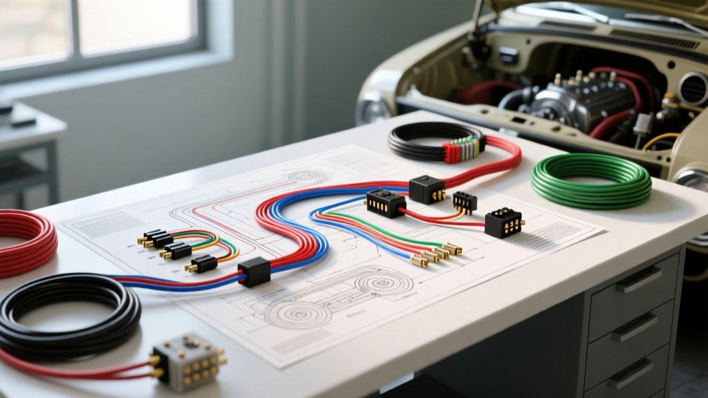
Introduction to Custom Auto Electrical & AC Retrofits
Integrating modern climate control into classic vehicles requires a meticulous approach to electrical architecture. When executing a classic car retrofit, following a structured Arts Auto Electric & Air Conditioning diagram walkthrough ensures that high-draw components like the electric AC compressor and blower motor do not overwhelm the factory charging system. Unlike factory harnesses designed for minimal loads, custom retrofits demand dedicated circuits, precise wire gauging, and robust relay switching to handle the inrush currents of magnetic AC clutches and high-amperage blower motors. This comprehensive guide breaks down the complete wiring methodology for a custom AC and charging system upgrade, utilizing industry-standard components and SAE-compliant routing practices.
Core Architecture of the Custom AC & Charging System
The foundation of any reliable automotive air conditioning electrical system is a high-output alternator paired with a dedicated power distribution block. For this walkthrough, we assume the installation of a 120-Amp 1-Wire or 3-Wire alternator (such as a Delco 12SI or Powermaster equivalent) and a Sanden SD7H15 rotary compressor with an electromagnetic clutch. The system is divided into three primary circuits: the main charging feed, the AC compressor clutch engagement circuit, and the blower motor speed control circuit. By isolating these circuits, we prevent voltage drop from affecting the vehicle's ignition system or ECU.
Complete Wiring Diagram Walkthrough: Circuit by Circuit
Circuit 1: Main Power and Alternator Feed
The alternator must be connected directly to the battery or the starter solenoid main post to minimize resistance. For a 120A alternator, a 4 AWG SXL (Cross-Linked Polyethylene) wire is required to handle the maximum continuous output and withstand the high ambient temperatures near the engine block. A 150A Mega Fuse or ANL fuse must be installed within 18 inches of the battery positive terminal to protect the main feed wire in the event of a short circuit. If utilizing a 3-wire alternator, the #1 terminal (voltage sense) must be wired directly to the main power distribution block using a 14 AWG wire, ensuring the alternator regulates voltage based on the actual load center, not the alternator output post.
Circuit 2: Electric AC Compressor Clutch & Relay
The Sanden SD7H15 clutch coil typically exhibits a resistance of 3.5 to 4.5 ohms, drawing roughly 3.5 to 4 amps at 14.2 volts. However, the initial inrush current can spike significantly higher. Directly switching the clutch via a dashboard toggle switch or mechanical thermostat will rapidly burn out the switch contacts. Instead, a standard automotive 30A SPST (Single Pole, Single Throw) Bosch-style relay is mandatory.
- Pin 30 (Common): Fed by a 10 AWG red wire from the fused power distribution block (protected by a 20A Maxi fuse).
- Pin 87 (Normally Open): Outputs to the AC compressor clutch coil via a 14 AWG light green wire. This connection must utilize a sealed Metri-Pack 280 connector to prevent moisture ingress and corrosion.
- Pin 85 (Ground): Tied to a clean, bare metal chassis ground using a 14 AWG black wire and a ring terminal with a star washer.
- Pin 86 (Trigger): Receives 12V from the AC thermostat or binary safety switch via a 16 AWG blue wire.
Expert Tip: To protect the relay contacts from the inductive voltage spike (back-EMF) generated when the clutch coil disengages, solder a 1N5408 flyback diode across the clutch coil wires at the compressor connector, with the diode stripe facing the positive feed.
Circuit 3: Blower Motor and Resistor Pack
Aftermarket blower motors, such as the Spal or Vintage Air units, can draw up to 18 amps on the highest speed setting. The main power feed to the blower motor switch or resistor block must be 10 AWG, protected by a 25A ATO fuse. The speed settings are achieved by routing the power through a ceramic resistor pack. The wiring from the resistor pack to the blower motor should be 12 AWG. Ensure the resistor pack is mounted in the HVAC plenum or an area with adequate airflow, as the resistors generate substantial heat on lower speed settings.
Pinout and Connector Specification Table
| Circuit Component | Wire Gauge (AWG) | Wire Color Code | Connector Type | Protection / Fuse |
|---|---|---|---|---|
| Alternator Main Output | 4 AWG SXL | Red | Ring Terminal (3/8') | 150A ANL Fuse |
| Alternator Sense (Pin #1) | 14 AWG | White | Spade / Bullet | 10A Inline ATO |
| AC Relay Feed (Pin 30) | 10 AWG | Red | Weather-Pack | 20A Maxi Fuse |
| AC Clutch Coil (Pin 87) | 14 AWG | Light Green | Metri-Pack 280 | Protected by Relay |
| Blower Motor High Speed | 10 AWG | Yellow | Weather-Pack | 25A ATO Fuse |
Wire Routing and SAE J1128 Compliance
Adhering to the SAE J1128 Standard for low-tension primary cable is critical in custom auto electrical work. SXL wire is preferred over standard GPT wire for engine bay routing due to its higher temperature rating (up to 125°C) and superior abrasion resistance. When routing the AC clutch and blower motor wires, maintain a minimum clearance of 6 inches from exhaust manifolds and moving components like the serpentine belt. All wires passing through the firewall must be protected by a rubber grommet and sealed with dielectric grease to prevent moisture from entering the cabin. For detailed alternator wiring best practices and voltage drop mitigation, the MAD Enterprises Alternator Tech Guide remains an invaluable resource for custom fabricators.
Troubleshooting Common AC Electrical Faults
Even with a flawless diagram walkthrough, real-world installations can present electrical anomalies. Use this decision tree to diagnose common AC electrical faults:
- Symptom: AC Clutch clicks rapidly but does not engage.
Cause: Severe voltage drop at the clutch coil or a failing binary pressure switch.
Fix: Measure voltage directly at the Metri-Pack 280 clutch connector while the system is calling for cooling. If voltage is below 11.5V, trace the 14 AWG green wire back to the relay Pin 87 to find the high-resistance fault. Check for loose crimps using a pull-test. - Symptom: Blower motor only works on High speed.
Cause: Blown resistor pack or melted connector at the resistor block.
Fix: Inspect the ceramic resistor block. High current on lower speeds often melts standard spade connectors. Upgrade to sealed Weather-Pack Connectors and apply dielectric grease to prevent future thermal degradation. - Symptom: Alternator whines and headlights pulse when AC compressor engages.
Cause: Inadequate alternator ground or undersized main power wire.
Fix: Verify the alternator case ground. Add a dedicated 4 AWG ground strap from the alternator casing directly to the engine block. Ensure the main 4 AWG output wire is not routed parallel to ignition wires, which can induce electromagnetic interference (EMI).
Final Crimping and Termination Standards
The longevity of an Arts Auto Electric & Air Conditioning style harness relies entirely on termination quality. Never use solder-only connections in high-vibration automotive environments; solder can wick under the wire insulation, creating a rigid point that will eventually snap from engine vibration. Always use open-barrel or closed-barrel mechanical crimps with the correct ratcheting tool, followed by adhesive-lined dual-wall heat shrink tubing. This ensures a gas-tight seal that prevents oxygen and moisture from causing galvanic corrosion inside the copper strands, guaranteeing a reliable climate control system for years to come.