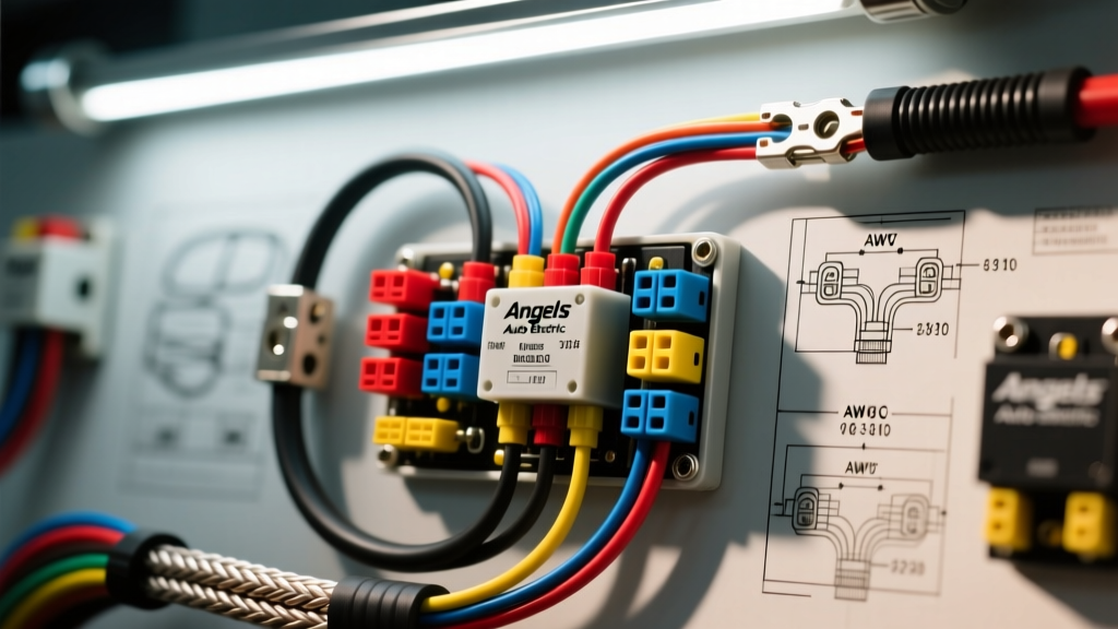
The Angels Auto Electric Standard for Custom Lighting Upgrades
When executing high-end aftermarket lighting modifications—specifically custom "Angel Eyes" (halo rings) and auxiliary LED light bars—industry-leading custom shops like Angels Auto Electric set the benchmark for flawless, factory-integrated harnesses. A premium upgrade project is not merely about connecting wires; it requires a deep understanding of vehicle electrical architecture, CAN-bus logic, and aerospace-grade termination standards. This guide details the exact methodology for building a custom halo and auxiliary lighting harness that rivals OEM specifications, ensuring long-term reliability and zero interference with the vehicle's Body Control Module (BCM).
Wire Selection: GXL/TXL vs. Standard PVC
The foundation of any Angels Auto Electric inspired build is the rejection of standard hardware-store THHN or PVC-coated wire. Under-hood environments expose wiring to extreme heat, vibration, and chemical solvents. For custom automotive harnesses, you must use cross-linked polyethylene (XLPE) insulated wire, specifically GXL or TXL, as outlined in the SAE J1128 standard. These thin-wall, high-temperature wires allow for tighter harness wrapping and superior resistance to abrasion.
| Wire Type | AWG Size | Insulation | Max Ampacity | Application in Custom Harness |
|---|---|---|---|---|
| TXL | 18 AWG | XLPE (Thin-wall) | 6A | Halo rings, LED marker lights, CAN-bus signal taps |
| GXL | 14 AWG | XLPE (Standard) | 15A | Auxiliary LED pods, relay trigger feeds |
| GXL | 10 AWG | XLPE (Standard) | 30A | Main power feeds from battery to distribution block |
| GXL | 8 AWG | XLPE (Standard) | 40A | High-draw LED light bars (50-inch+), winch solenoids |
Harness Architecture: Bosch Relays and Power Distribution
Never tap factory headlight circuits directly to power high-draw auxiliary lights or multiple halo rings. Modern vehicles use multiplexed LIN/CAN-bus networks and low-current PWM (Pulse Width Modulation) signals to drive lighting. Drawing excess current will trigger a BCM fault, shutting down the circuit entirely. Instead, use the factory signal solely as a low-current trigger for an automotive relay.
Standard 4-Pin ISO Mini Relay Pinout
For auxiliary lighting and halo power distribution, the standard Bosch-style ISO mini relay is the industry workhorse. Below is the precise pin configuration and color-coding standard used in premium custom builds:
- Pin 30 (Common Input): 10 AWG Red wire. Connects directly to the battery positive terminal via an inline MAXI fuse (rated 125% of the total load).
- Pin 87 (Normally Open Output): 14 AWG Yellow wire. Routes to the auxiliary lights or halo ring power distribution block.
- Pin 86 (Coil Positive): 18 AWG Blue wire. Connects to the ignition-switched 12V+ source or the output of a CAN-bus trigger module.
- Pin 85 (Coil Ground): 18 AWG Black wire. Terminated to a clean, bare-metal chassis ground point, secured with a star washer and treated with di-electric grease.
CAN-Bus Integration and DRL Logic Modules
Integrating halo rings as Daytime Running Lights (DRLs) on modern platforms (e.g., 2018-2023 Jeep Wrangler JL or 2019+ RAM 1500) requires bypassing the BCM's "bulb-out" detection algorithms. If you wire halos directly to the DRL circuit, the BCM will detect an unexpected resistance load and hyper-flash or disable the circuit.
To solve this, premium integrators use a logic interface module, such as a PAC TR-4 or a dedicated CAN-bus decoder. These modules monitor the factory CAN-bus data lines or sense the low-current PWM signal without drawing enough amperage to trigger a fault. The module then outputs a clean, steady 12V+ 2A signal to trigger your custom relay harness. When routing these signal wires, ensure they are shielded or routed at least 6 inches away from high-voltage ignition coils or alternator stator wires to prevent Electromagnetic Interference (EMI).
Fuse Sizing and Circuit Protection Mathematics
Proper circuit protection is non-negotiable in custom automotive electrical projects. Fuses are designed to protect the wire, not the load. To calculate the correct MAXI or ATO blade fuse size, you must determine the maximum continuous current draw of your lighting array and apply a 125% safety margin, while ensuring the fuse rating never exceeds the ampacity of the wire gauge used.
For example, if you are wiring a set of four 3-inch LED halo pods that draw 1.5A each (Total = 6A), and you are using 14 AWG GXL wire (rated for 15A), your calculation is 6A x 1.25 = 7.5A. You would select an 8A or 10A ATO blade fuse. If a short circuit occurs, the 10A fuse will blow long before the 14 AWG wire reaches its thermal melting point, preventing an under-hood electrical fire. Always mount the fuse holder within 18 inches of the battery positive terminal to ensure the entire length of the main power feed is protected.
Weatherproofing and Termination Protocols
The difference between a garage hack and an Angels Auto Electric level build lies in the terminations. Electrical tape and twist-on wire nuts are strictly prohibited. All connections in the engine bay or exterior body panels must utilize environmental seals.
Deutsch DT Connector Crimping
For detachable connections at the auxiliary lights or halo pigtails, use Deutsch DT series connectors. These thermoplastic housings feature silicone rear grommets that seal the wires completely against moisture ingress.
- Strip exactly 5/32 inch of insulation from the GXL/TXL wire.
- Insert the bare wire into the open-barrel Deutsch contact.
- Use a precision open-barrel crimp tool (e.g., Hozan P-707) to crimp the wire barrel, ensuring the wire strands are flush with the front of the crimp.
- Crimp the insulation grip to secure the XLPE jacket.
- Insert the contact into the DT housing until the stainless steel retention tang clicks into place.
- Insert the orange or green silicone wedge seal into the rear cavity to lock the contact and seal the wire.
Diagnostic Troubleshooting for Custom LED Circuits
Even with meticulous planning, custom lighting upgrades can present unique electrical anomalies. Use this diagnostic tree to isolate faults in your halo and auxiliary lighting harness:
Symptom: LED Halos Flicker Rapidly (PWM Flicker)
Cause: The factory DRL circuit uses Pulse Width Modulation (PWM) to dim the lights, switching the voltage on and off hundreds of times per second. While incandescent bulbs smooth this out via thermal inertia, LEDs react instantly, causing visible strobing.
Fix: Install a PWM filter module (a simple capacitor and diode array) inline between the factory trigger wire and the relay coil (Pin 86). The capacitor stores the charge during the "off" cycles, providing a smooth, continuous 12V+ signal to the relay coil.
Symptom: Voltage Drop at the Auxiliary Light Bar
Cause: Undersized wire gauge for the distance traveled, or poor ground termination. A 50-inch LED bar drawing 12A over a 15-foot run of 16 AWG wire will suffer a severe voltage drop, resulting in dim output and overheated wires.
Fix: Measure voltage at the battery, then at the relay Pin 30, and finally at the light bar connector under load. If the drop exceeds 0.5V, upgrade the power and ground feed to 10 AWG GXL wire. Always ensure the ground path is equally as robust as the positive feed; a poor ground creates resistance that mimics a voltage drop on the positive side.
Conclusion
Executing an Angels Auto Electric standard lighting upgrade requires moving beyond basic wire-tapping and embracing automotive-grade harness fabrication. By utilizing SAE J1128 compliant TXL/GXL wiring, properly rated Bosch relays, CAN-bus logic interfaces, and sealed Deutsch terminations, you ensure your custom halo rings and auxiliary light bars operate flawlessly for the life of the vehicle. Always document your custom pinouts and fuse ratings inside the vehicle's glovebox for future diagnostic reference.