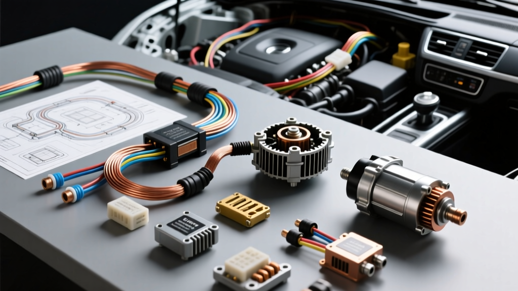
The Landscape of Auto Electric Rebuilders
When sourcing components for alternator and starter overhauls, the term auto electric rebuilders often refers to the foundational Tier 1 and Tier 2 manufacturers that supply OE-spec kits to local repair shops and remanufacturing facilities. Selecting the right rebuild kit is not merely about finding the lowest price; it is about matching the exact electrical architecture of modern vehicle charging systems. A substandard voltage regulator or rectifier bridge can lead to catastrophic PCM (Powertrain Control Module) failure due to load dump spikes or CAN/LIN bus communication errors.
In this product comparison and selection guide, we evaluate the top component suppliers—specifically Transpo Electronics, Lester Electrical, and ZEN Industries—breaking down their alternator rectifiers, LIN/BSS regulators, and starter solenoids to help you select the right kit for your specific application.
Transpo vs. Lester vs. ZEN: Component Comparison
Rectifier Bridges and Avalanche Diodes
The rectifier bridge converts the alternator's AC stator output to DC. Modern vehicles require avalanche diodes to handle load dump transients as defined by ISO 7637-2 Pulse 5. When a battery cable is disconnected while the engine is running, the alternator can generate voltage spikes exceeding 80V. Avalanche diodes safely clamp these spikes by conducting in reverse breakdown mode, protecting sensitive vehicle electronics.
- Transpo: Widely considered the gold standard for OE-replacement rectifiers. Their avalanche diode arrays feature superior thermal coupling to the heat sink plates, critical for high-output Denso and Bosch units. Transpo utilizes high-temperature solder joints that resist micro-cracking under thermal cycling.
- Lester Electrical: Offers robust, cost-effective bridges. Excellent for standard 100A-130A applications. However, for high-demand applications (e.g., 200A+ towing packages), their thermal dissipation profiles may run slightly hotter than Transpo equivalents.
- ZEN Industries: Specializes heavily in starter drives and solenoids, but their rectifier offerings are generally limited to older, non-LIN regulated alternators. Best suited for classic car or heavy-duty agricultural rebuilds.
Voltage Regulators and PCM Communication (LIN/BSS)
Mechanical and early solid-state regulators are obsolete in modern architectures. Today's auto electric rebuilders must supply regulators capable of decoding PWM (Pulse Width Modulation) and LIN (Local Interconnect Network) signals from the PCM.
Take the Denso SC1 and SC2 alternator platforms as an example. The regulator plug typically features up to 6 terminals: L (Lamp), IG (Ignition), S (Sense), C (Computer/ECU), P (Phase), and DF (Field). A high-quality Transpo regulator will accurately interpret the PCM's duty cycle requests on the C terminal, adjusting rotor field current within milliseconds to maintain a strict 14.2V to 14.8V target based on battery temperature sensors. Budget aftermarket regulators often default to a fixed 14.4V internal map, ignoring the PCM's deceleration fuel cut-off (DFCO) voltage bump requests, which triggers a Check Engine Light (e.g., OBD-II code P0620).
Starter Solenoids & Contact Plates
For starter rebuilds, the solenoid is the primary wear item. When comparing auto electric rebuilders for starter kits, inspect the main contact plates. ZEN Industries excels here, providing solid copper contact plates with silver alloy facing. Budget kits often use aluminum plates with copper plating; once the plating wears through (usually around 30,000 cycles), the aluminum arcs heavily, causing the starter to 'click' without cranking. Furthermore, ZEN solenoids feature precise hold-in and pull-in winding ratios, ensuring the shift fork engages the ring gear smoothly without gear clash.
Technical Specifications & Failure Modes
Use the following specification chart to diagnose component failures and verify the quality of your selected rebuild kit.
| Component | OE Specification | Budget Aftermarket Spec | Common Failure Mode |
|---|---|---|---|
| Alternator Brushes | Copper-graphite, 15mm new / 10mm min wear | Standard carbon, high dust generation | Slip ring grooving, rotor open circuit |
| Brush Spring Tension | 2.5 N to 3.2 N (Newtons) | 1.5 N to 2.0 N | Brush bounce at high RPM, intermittent charging |
| Regulator Sense Circuit | Direct B+ tie, < 50mV drop | Internal sense only | Undercharging at battery, overcharging at alternator |
| Starter Solenoid Contacts | Solid copper w/ silver facing | Steel w/ copper flash plating | High amperage voltage drop, no-crank condition |
Bench Testing Rebuilt Units: Wiring & Pinouts
Once you have assembled your alternator using premium components from top auto electric rebuilders, rigorous bench testing is mandatory. Relying on the vehicle's wiring harness to 'break in' a new regulator is a recipe for comebacks. Follow this wiring protocol for your test bench:
Test Bench Wiring Harness Requirements
- Main Power (B+): Use 4 AWG oxygen-free copper wire from the bench battery positive to the alternator B+ terminal. Torque the M8 nut to 12-15 Nm. Do not use 8 AWG; the instantaneous inrush current during load testing will melt the insulation.
- Ignition Trigger (IG): Use 14 AWG wire with an inline 30A maxi-fuse to switch 12V to the IG terminal.
- Sense Terminal (S): This is the most critical wiring step. Run a dedicated 12 AWG wire directly from the B+ output post to the S terminal on the regulator plug. If you rely on internal sensing or a thin 18 AWG jumper, the regulator will read a false low-voltage state and overcompensate, potentially boiling the battery.
- PCM Simulator (LIN/COM): For modern LIN-controlled alternators (e.g., Bosch LIN2), you must use a dedicated LIN simulator tool. Connect the simulator using 18 AWG shielded twisted pair (STP) wire to prevent EMI interference from the test bench motor from corrupting the 12V square-wave duty cycle signal.
Diagnostic Decision Tree: Voltage Regulator Failures
If your newly rebuilt unit fails the bench test, use this diagnostic tree before discarding the regulator:
- Symptom: Alternator outputs exactly 13.5V and will not increase under load.
Cause: Open circuit in the rotor field winding or worn slip rings.
Fix: Measure resistance across the slip rings. Expected: 2.5 to 4.0 ohms. If infinite, check the internal solder joints connecting the brush pigtails to the regulator spades. - Symptom: Alternator outputs 16.5V+ (Overcharging).
Cause: Loss of ground reference or open Sense (S) circuit.
Fix: Verify the alternator case is grounded to the bench battery negative using a 6 AWG ground strap. Check the S-terminal wire for continuity. According to SAE J56 Alternator Test Procedures, any voltage drop on the sense circuit will cause the regulator to max out field current. - Symptom: AC Ripple exceeds 300mV.
Cause: Blown diode in the rectifier bridge or loose stator lead connection.
Fix: Inspect the stator-to-rectifier solder joints. Many budget kits use press-fit connections which vibrate loose. Always reflow these joints with high-temperature rosin-core solder.
Final Selection Verdict
When choosing between auto electric rebuilders for your shop or personal garage, Transpo remains the undisputed leader for late-model, PCM-controlled alternators due to their flawless LIN protocol decoding and OE-grade avalanche diodes. Lester Electrical provides excellent value for high-volume, standard-output remanufacturing. For starter drives and heavy-duty solenoids, ZEN Industries offers the most durable copper-contact assemblies. Always pair these premium internal components with precision-machined slip rings and high-tension brush holders to ensure the rebuilt unit meets or exceeds the original manufacturer's electrical specifications.