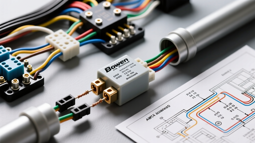
Upgrading Your Rig: The Bowen Auto Electrical Auxiliary Relay Kit
Modern off-road, overland, and commercial vehicles demand massive electrical overhead. Factory alternators and OEM fuse boxes are engineered for stock loads, leaving minimal headroom for high-draw accessories like 50-inch LED light bars, 12,000-lb winches, onboard air compressors, and dual-battery isolators. Attempting to route these heavy loads through factory cabin switches or stock wiring harnesses inevitably leads to melted connectors, severe voltage drop, and potential electrical fires. The Bowen Auto Electrical auxiliary relay and power distribution kit provides a robust, isolated, and high-amperage circuit architecture designed specifically for these demanding applications.
This comprehensive installation guide details the professional integration of the Bowen Auto Electrical system into your vehicle. We will cover wire gauge selection, crimping methodologies, ISO 7588 relay pinouts, and rigorous voltage-drop testing to ensure your auxiliary electrical system performs flawlessly under extreme environmental conditions.
Pre-Installation: Wire Gauge and Material Requirements
Before cutting into the Bowen Auto Electrical harness or tapping into your battery, you must verify your wire gauge and insulation type. For primary power feeds in engine bays, standard PVC-insulated wire is insufficient due to high ambient temperatures and exposure to corrosive fluids. We mandate the use of SAE J1128 SGX (cross-linked polyethylene) or premium welding cable for all main power and ground runs. SGX insulation offers superior resistance to heat, abrasion, and battery acid, ensuring long-term reliability in harsh under-hood environments.
| AWG Size | Max Continuous Amps | Primary Use Case in Bowen Kit | Recommended Fuse (ANL) |
|---|---|---|---|
| 4 AWG | 120A | Main Battery Feed to Distribution Block | 100A - 125A |
| 8 AWG | 50A | Winch Solenoid / Heavy Compressor Feed | 60A |
| 10 AWG | 30A | LED Light Bar / Dual Battery Isolator | 30A - 40A |
| 14 AWG | 15A | Relay Trigger Wire / Cabin Switch Feed | 10A (ATM) |
Crimping Methodologies: Hex vs. Indent
When terminating 4 AWG and 8 AWG wires for the Bowen Auto Electrical distribution block, the crimp profile is critical. Avoid cheap indent-style crimpers that bite into the copper strands; these create localized stress points and reduce the cross-sectional area of the conductor, leading to hot spots. Instead, use a dedicated hex-crimp tool. A hex crimp uniformly compresses the copper and the terminal barrel into a solid, cold-welded mass, maximizing surface contact and minimizing electrical resistance. Always finish the termination with adhesive-lined, dual-wall heat shrink to seal out moisture and prevent galvanic corrosion at the terminal joint.
Step-by-Step Installation Procedure
Step 1: Primary Power Feed and ANL Fuse Placement
The most critical safety component in any auxiliary wiring system is the overcurrent protection device. According to ABYC and SAE safety standards, the main fuse must be located as close to the power source as physically possible. For the Bowen Auto Electrical kit, install an ANL fuse holder within 18 inches of the positive battery terminal. If the 4 AWG power cable were to chafe against the chassis before reaching the relay block, the ANL fuse will instantly sever the circuit, preventing a catastrophic short-to-ground fire. Use a heavy-duty brass battery terminal clamp with a secondary stud to attach your 4 AWG ring terminal, ensuring the OEM positive cable remains undisturbed.
Step 2: Mounting the Bowen Distribution Block
Locate a dry, well-ventilated area in the engine bay or behind the front grille to mount the Bowen distribution block. Avoid areas directly above the exhaust manifold or near the radiator fan shroud where debris impact is likely. Use stainless steel hardware and nylon lock nuts to secure the block. Before tightening the terminal set-screws on the distribution block, apply a thin layer of dielectric grease to the exposed copper. This prevents oxidation, which can increase resistance and cause the block to overheat under sustained high-amperage loads.
Step 3: Relay Pinout and Trigger Wire Configuration
The Bowen Auto Electrical kit utilizes heavy-duty, ISO 7588 standard 5-pin Bosch-style relays (typically rated for 40A continuous). Understanding the pinout is essential for proper switching logic and preventing backfeed into sensitive vehicle CAN-bus systems.
| Relay Pin | Standard Color Code | Function & Connection Point |
|---|---|---|
| Pin 30 | Red (4 AWG / 8 AWG) | Common Input: Connects to the fused main power from the Bowen distribution block. |
| Pin 87 | Red (Load Specific) | Normally Open (NO) Output: Routes power to the accessory (e.g., LED bar) when the relay is energized. |
| Pin 86 | Yellow / Blue (14 AWG) | Coil Positive: Connects to the 12V+ trigger source (e.g., high-beam wire, ignition switch, or manual cabin toggle). |
| Pin 85 | Black (14 AWG) | Coil Ground: Must be grounded to a clean, bare-metal chassis point. Do not ground to painted surfaces. |
| Pin 87a | Not Used | Normally Closed (NC): Left empty or insulated in standard auxiliary lighting applications. |
Expert Tip: If your trigger source is a solid-state switch or a modern vehicle's BCM (Body Control Module), the relay coil's collapsing magnetic field can generate a high-voltage flyback spike (up to 100V) that may damage sensitive vehicle computers. To protect the OEM electronics, solder a 1N4001 flyback diode across the relay coil terminals (Pin 85 and Pin 86), with the diode's cathode (striped end) facing the 12V+ trigger source (Pin 86).
Step 4: Grounding and Circuit Routing
A circuit is only as good as its ground. For high-draw accessories powered by the Bowen kit, do not rely on the accessory's internal chassis ground. Run a dedicated ground wire (equal in AWG to the positive feed) back to a centralized ground bus bar or directly to the negative battery terminal. If grounding to the chassis, use a rotary burr or sandpaper to remove all paint, powder coat, and rust down to bare, shiny steel. Secure the ring terminal with a stainless steel bolt and a star washer to bite into the metal, then coat the entire connection in battery terminal protector spray to halt flash rust.
Testing and Validation: The Voltage Drop Method
Never rely solely on a test light to validate a heavy-current circuit. A test light will illuminate even if the wire is severely undersized and dropping 4 volts, which will result in dim lights and slow winch motors. Instead, use a digital multimeter (DMM) set to DC Volts to perform a dynamic voltage drop test while the accessory is under load.
- Test the Positive Side: Place the red multimeter probe on the positive battery terminal and the black probe on the accessory's positive input pin. With the accessory running, the reading should be less than 0.5V. If it reads higher, you have excessive resistance (bad crimp, corroded terminal, or undersized wire) on the positive feed.
- Test the Ground Side: Place the red probe on the accessory's ground pin and the black probe on the negative battery terminal. The reading should be less than 0.1V. A higher reading indicates a poor chassis ground or a corroded battery negative clamp.
- Test the Fuse: Place one probe on each side of the ANL fuse while under load. A healthy fuse will drop less than 0.05V. If you read 0.5V or more across the fuse, the fuse holder terminals are loose or oxidized.
Troubleshooting Common Installation Faults
- Symptom: Relay clicks rapidly or chatters when the switch is engaged.
Cause: Severe voltage drop on the 14 AWG trigger wire (Pin 86). The relay coil is not receiving enough voltage to hold the electromagnet closed, causing it to oscillate.
Fix: Check for undersized trigger wires, long unamplified switch runs, or a poor ground on Pin 85. Consider using a secondary micro-relay to trigger the main Bowen relay. - Symptom: Accessory receives power even when the cabin switch is off.
Cause: Backfeed through a shared OEM circuit (e.g., tapping into the high-beam wire on a modern multiplexed CAN-bus system).
Fix: Install a blocking diode on the trigger wire, or use an isolated trigger module that reads the magnetic field around the OEM wire without physically piercing the insulation. - Symptom: ANL fuse blows instantly upon engaging the winch.
Cause: Inrush current spike exceeding the fuse's interrupt rating, or a direct short-to-ground.
Fix: Verify the winch solenoid is functioning correctly. If no short is present, upgrade to a time-delay (slow-blow) ANL fuse of the same amperage rating to handle the initial motor startup surge.
Authoritative References and Standards
Proper automotive electrical design requires adherence to established engineering standards. The methodologies outlined in this Bowen Auto Electrical installation guide are based on the following industry benchmarks:
- SAE J1128: Low Tension Primary Cable - Defines the thermal and physical requirements for automotive wire insulation, including the SGX cross-linked polyethylene standard recommended for engine bay routing.
- Littelfuse ANL Fuse Datasheets - Provides critical data on interrupting capacity, voltage drop limits, and time-current curves for high-amperage automotive overcurrent protection.
- SAE J1284: Battery Clamps - Outlines the mechanical and electrical performance requirements for battery terminal connectors to ensure secure, low-resistance primary power connections.