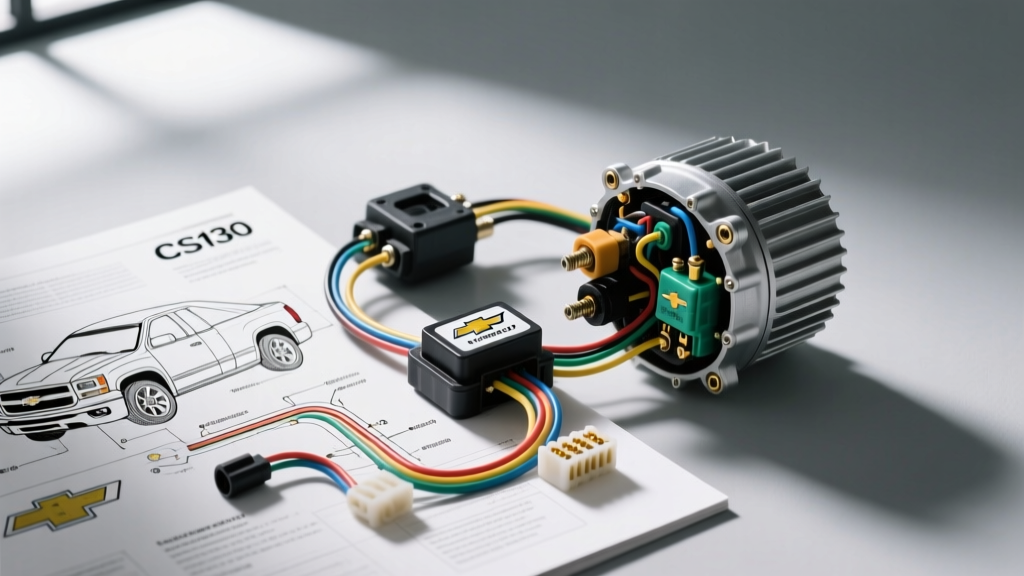
Introduction to OBS Cheyenne Electrical Weaknesses
Owners searching for auto electric Cheyenne solutions are usually dealing with two notorious issues inherent to the 1988-1998 Chevrolet C/K OBS (Old Body Style) platform: dim, flickering headlights and undercharging alternators. The factory wiring architecture on the Cheyenne trim routes the entire headlight current load (often exceeding 12 amps) directly through the dash-mounted headlight switch using marginal 14 AWG wire. Over decades, this causes severe voltage drop, melted switch connectors, and poor illumination.
Furthermore, the factory Delco alternators—whether the aging 10SI on earlier models or the early CS130 units—are often compromised by poor remote voltage sensing and degraded exciter circuits. This comprehensive how-to guide will walk you through a complete front-end electrical overhaul, utilizing heavy-gauge wiring, Bosch-style relays, and proper Delco CS130 alternator pinning to modernize your truck's electrical architecture.
Phase 1: Headlight Relay Harness Installation
The goal of this phase is to remove the high-amperage load from the factory dash switch. The switch will only act as a low-amperage trigger for a set of 30A SPDT (Single Pole Double Throw) relays mounted in the engine bay, which will pull power directly from the battery.
Required Materials & Wire Specifications
- Power Feed Wire: 10 AWG Red stranded copper (rated for 30A continuous).
- Trigger Wire: 14 AWG (matching factory colors: Light Green for low beam, Tan for high beam).
- Relays: Two 12V 30A Bosch-style ISO Mini Relays (Standard 5-pin, using 4).
- Fuses: Two 30A Maxi-Fuses with inline weatherproof holders.
- Connectors: Adhesive-lined heat shrink ring terminals and butt splices to prevent corrosion.
Relay Pinout & Wiring Steps
| Relay Pin | Function | Wire Color / Gauge | Connection Point |
|---|---|---|---|
| 30 | 12V+ Constant Power In | 10 AWG Red | Battery Positive (via 30A Maxi-Fuse) |
| 87 | 12V+ Switched Power Out | 10 AWG Red | Headlight H6054/H4656 Plug (Hot Pin) |
| 86 | Trigger In (from Dash) | 14 AWG Light Green / Tan | Spliced into factory headlight trigger wire |
| 85 | Ground | 12 AWG Black | Clean firewall or radiator core support stud |
Step 1: Route the Main Power. Run a continuous length of 10 AWG Red wire from the battery positive terminal to the engine bay relay mounting location. Install a 30A Maxi-Fuse within 6 inches of the battery terminal. Crimp a 3/8-inch ring terminal using a closed-barrel crimper and seal with adhesive heat shrink.
Step 2: Tap the Factory Trigger Wires. Locate the factory headlight harness near the radiator support. Using a Painless Performance wiring guide as a reference, identify the Light Green wire (Low Beam) and Tan wire (High Beam). Use a Posi-Tap connector to tap into these wires with your 14 AWG trigger wires. This ensures the dash switch only carries the <1 amp relay coil current.
Step 3: Wire the Outputs. Connect Pin 87 of each relay to the corresponding hot terminal on the new ceramic headlight pigtail sockets. Ensure the ground pins on the headlight sockets are tied to a dedicated 12 AWG Black ground wire bolted directly to the core support, bypassing the factory ground path which is prone to rust.
Phase 2: Upgrading to the Delco CS130 Alternator
Many Cheyenne trucks suffer from dim lights at idle because the factory voltage regulator relies on a poorly routed sense wire. Upgrading to a high-output (105A to 140A) Delco CS130 alternator requires understanding the 4-pin connector logic. According to Mad Electrical's remote voltage sensing guidelines, proper wiring of the 'S' terminal is critical for stable system voltage.
CS130 4-Pin Connector Configuration
| Terminal | Label | Function | Wiring Requirement |
|---|---|---|---|
| L | Lamp / Exciter | Turns on dash 'GEN' light and excites the rotor field to begin charging. | Connect to factory Brown/White wire (Dash Lamp). Must have 12V ignition switched source. |
| F | Field | Provides PCM/ECM field duty cycle data (OBD-II era). | Leave disconnected and taped back on pre-OBDII OBS trucks. |
| P | Phase | Stator phase output for tachometers or fuel pump relays. | Leave disconnected unless specifically required by an aftermarket accessory. |
| S | Sense | Reads actual battery/system voltage to regulate output. | CRITICAL: Run 10 AWG Red wire directly to Battery (+) or Main Junction Block with a 10A inline fuse. |
The Sense Wire Fix: The factory Cheyenne wiring often routes the Sense wire to the alternator output stud itself. This means the regulator reads voltage at the alternator, not the battery, leading to undercharging when accessories are on. Run a dedicated 10 AWG Red wire from the 'S' terminal on the alternator pigtail directly to the positive battery post or the main firewall junction block. Install a 10A AGC inline glass fuse near the battery end to protect the sense circuit from a dead short.
Phase 3: Addressing OBS Cheyenne Ground Disease
No auto electric Cheyenne project is complete without addressing the platform's notorious ground issues. The OBS C/K trucks rely on several critical ground points that corrode from road salt and moisture.
- Firewall to Engine Block: Locate the braided ground strap on the passenger side firewall. Remove it, wire-brush the sheet metal and the cylinder head bolt surface to bare metal, apply dielectric grease, and re-secure with a Grade 8 bolt.
- Bed to Frame Ground: The fuel pump and tail lights ground through the bed. Locate the 12 AWG Black wire near the rear driver-side frame rail. If the ring terminal is corroded, cut it back, strip the wire, and crimp a new tinned ring terminal.
- Tail Light Socket Pigtails: If your Cheyenne's tail lights backfeed (e.g., pressing the brake pedal makes the turn signal blink dimly), the socket ground is failing. Replace the factory sockets with heavy-duty ceramic pigtails and run a dedicated 14 AWG ground wire from the socket shell directly to the frame.
Troubleshooting Decision Tree: Alternator Not Charging
If you have completed the CS130 upgrade but the voltmeter reads 12.2V or less with the engine running, follow this diagnostic path:
- Check the Dash Lamp: Turn the key to 'ON' (engine off). Does the 'GEN' or 'BATT' light illuminate?
- No: The 'L' terminal is not receiving ignition-switched 12V. Check the Brown/White wire for continuity and ensure the dash bulb is not burnt out (a burnt bulb breaks the exciter circuit).
- Yes: Proceed to Step 2.
- Check the Sense Wire: Start the engine. Measure voltage at the alternator output stud, then measure at the battery positive post.
- Voltage at alternator is 14.2V, but battery is 12.8V: You have massive voltage drop in the main charge wire or a bad engine block ground. Upgrade the alternator-to-battery positive cable to 4 AWG.
- Voltage is 12.5V everywhere: The 'S' terminal wire is broken or the 10A inline fuse is blown. The regulator defaults to a limp-home mode (approx 13.0V) or shuts off if it loses the sense reference. Refer to the Haynes Chevrolet C/K Pick-Up Repair Manual for detailed multimeter back-probing procedures on the Delco pigtail.
Conclusion
By bypassing the factory headlight switch with a relay harness and properly wiring the remote sense terminal on a CS130 alternator, you effectively eliminate the most common electrical gremlins in the Cheyenne lineup. Using the correct AWG wire sizes, adhesive-lined terminals, and proper circuit protection ensures your classic OBS truck will have reliable, modern electrical performance for decades to come.