The Evolution of Custom Harness Architecture
When evaluating high-end aftermarket wiring methodologies for restomods, EV conversions, and custom motorsport builds, the protocols established by Chi's Auto Electric have become a benchmark for reliability and signal integrity. Unlike mass-produced OEM harnesses that prioritize cost-efficiency and automated assembly, the Chi's Auto Electric methodology focuses on extreme environmental resilience, minimized voltage drop, and flawless Controller Area Network (CAN-bus) integration. This advanced technical deep dive dissects the core wiring standards, connector architectures, and diagnostic protocols that define this elite tier of automotive electrical engineering.
Wire Selection: Moving Beyond Standard SAE J1128
Standard automotive primary wire, governed by SAE J1128 specifications (such as TXL and GXL), utilizes cross-linked polyethylene (XLPE) insulation. While adequate for standard passenger vehicles, custom high-performance applications demand higher thermal and chemical resistance. The Chi's Auto Electric specification frequently mandates the use of MIL-W-22759/16 PTFE (Tefzel) insulated wire for critical engine bay routing.
PTFE insulation allows for a thinner dielectric wall while maintaining superior resistance to aromatic hydrocarbons, synthetic oils, and extreme heat. This reduction in outer diameter allows for tighter bend radii and lighter overall harness weight, which is critical in aerospace and top-tier motorsport applications.
Table 1: Mil-Spec PTFE vs. Standard GXL Wire Ratings (Engine Bay Ambient 105°C)
| AWG Size | Insulation Type | Max Continuous Temp | Ampacity (Single Wire in Free Air) | Voltage Drop per 10ft @ Max Load |
|---|---|---|---|---|
| 18 AWG | GXL (XLPE) | 125°C | 16A | 0.41V |
| 18 AWG | PTFE (Mil-Spec) | 200°C | 20A | 0.41V |
| 14 AWG | GXL (XLPE) | 125°C | 32A | 0.16V |
| 14 AWG | PTFE (Mil-Spec) | 200°C | 40A | 0.16V |
| 10 AWG | PTFE (Mil-Spec) | 200°C | 75A | 0.06V |
Connector Architecture: AMPSEAL and Deutsch DTM Integration
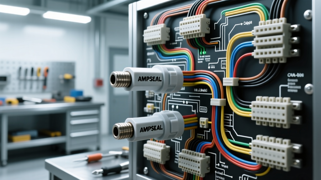
A harness is only as reliable as its terminations. The Chi's Auto Electric standard rejects standard weather-pack connectors in favor of TE Connectivity AMPSEAL 16 and Deutsch DTM series for ECU and sensor interfaces. These connectors utilize solid copper alloy pins with gold or tin plating, ensuring micro-ohm level contact resistance even under high-frequency vibration.
Precision Crimping and Pull-Force Specifications
Improper crimping is the leading cause of intermittent electrical faults. The Chi's Auto Electric protocol requires the use of pneumatic or precision ratcheting crimp tools calibrated to specific wire gauges. A proper crimp deforms the wire strands and the terminal barrel into a cold-weld state, eliminating voids where moisture could infiltrate and cause galvanic corrosion.
- 18-20 AWG Pins: Require a minimum pull-force of 15 lbs (66 N) to pass quality control.
- 14-16 AWG Pins: Require a minimum pull-force of 30 lbs (133 N).
- 10-12 AWG Pins: Require a minimum pull-force of 50 lbs (222 N).
Furthermore, dielectric grease (specifically non-conductive silicone-based compounds like Nyogel 760G) is applied to the connector cavities post-assembly to displace oxygen and prevent fretting corrosion on the tin-plated terminals.
CAN-Bus Topology and Signal Integrity
Modern engine management systems (such as Bosch Motronic, HP Tuners, and MoTeC) rely heavily on CAN-bus networks for telemetry, dash integration, and transmission control. The SAE J1939 and ISO 11898 standards dictate the physical layer of these networks, but custom installations often fail due to improper topology and termination.
Twisted Pair Routing and Shielding
CAN-High (CAN-H) and CAN-Low (CAN-L) must be routed as a twisted pair to cancel out electromagnetic interference (EMI) generated by alternators, ignition coils, and EV traction inverters. The Chi's Auto Electric standard mandates a minimum of 1.5 twists per inch for unshielded twisted pair (UTP) wiring in the engine bay. For high-EMI environments (such as near CDI ignition boxes), a shielded twisted pair (STP) with a dedicated 18 AWG drain wire grounded at the ECU end only is required to prevent ground loops.
Table 2: Standard CAN-Bus Pinout and Voltage Diagnostics
| Signal | Standard Wire Color | Recessive Voltage (Idle) | Dominant Voltage (Active) | Termination |
|---|---|---|---|---|
| CAN-High | Yellow (or White/Black Trace) | 2.50V | 3.50V | 120Ω to CAN-L |
| CAN-Low | Green (or White/Red Trace) | 2.50V | 1.50V | 120Ω to CAN-H |
| CAN-Shield | Bare / Braided | N/A | N/A | Grounded at ECU |
Diagnostic Insight: When diagnosing a CAN network built to these standards, an oscilloscope is mandatory. A multimeter will only show an average voltage of ~2.5V. However, an oscilloscope will reveal the differential signal. If the dominant voltage of CAN-H drops below 3.2V or CAN-L rises above 1.8V, it indicates excessive capacitance in the harness (often caused by running CAN wires parallel to high-voltage AC lines) or a failing transceiver inside the ECU.
Grounding Topology: Star vs. Daisy Chain
The most critical, yet frequently misunderstood, aspect of automotive electrical systems is the ground return path. The Chi's Auto Electric methodology strictly prohibits "daisy-chaining" grounds (connecting multiple sensors to a single ground wire that eventually reaches the chassis). Daisy-chaining introduces shared impedance; when a high-current device like a fuel pump activates, the voltage drop across the shared ground wire can offset the 0-5V reference signal of a MAP sensor, causing erratic fueling.
Implementing a Star Ground Distribution Block
Instead, a centralized "Star Ground" topology is utilized. A heavy-duty bus bar (minimum 4 AWG input from the battery negative terminal) is mounted in the engine bay. From this bus bar, individual ground wires are routed to specific subsystems:
- ECU Sensor Grounds: 14 AWG, dedicated directly to the ECU ground pins. Never shared with actuators.
- Injector/Coil Power Grounds: 12 AWG, routed to a secondary power-ground bus.
- Chassis/Body Grounds: 8 AWG or 6 AWG, ensuring the vehicle body is equipotential with the engine block.
All ground ring terminals must be crimped using a hex-crimp die, not an indentor crimper, to ensure maximum surface area contact. The mating surface on the engine block or chassis must be stripped of paint and powder coat down to bare metal, treated with a conductive anti-oxidant paste, and torqued to the manufacturer's specification (typically 9-11 Nm for an M6 stainless steel bolt).
Advanced Relay and Power Distribution Integration
Finally, the Chi's Auto Electric standard replaces traditional mechanical Bosch-style relays with solid-state power distribution modules (PDMs) or high-current PCB relays housed in sealed IP67 enclosures. Mechanical relays suffer from contact bounce, coil degradation, and internal arcing. By utilizing PDMs with integrated pulse-width modulation (PWM) capabilities, builders can precisely control fuel pump speeds based on ECU demand, reducing parasitic draw and heat generation in the fuel system. Fusing is handled via automotive-grade MIDI or MEGA fuses, rated for high interrupting capacity (up to 10,000A at 32V), ensuring the harness is protected against catastrophic dead-short scenarios.
Conclusion
Adopting the rigorous standards championed by Chi's Auto Electric transforms a vehicle's electrical system from a frequent point of failure into a bulletproof nervous system. By upgrading to Mil-Spec PTFE wiring, enforcing strict AMPSEAL crimping tolerances, meticulously terminating CAN-bus networks, and implementing star-ground topologies, automotive electrical engineers can guarantee signal integrity and long-term reliability in the most demanding motorsport and custom build environments.