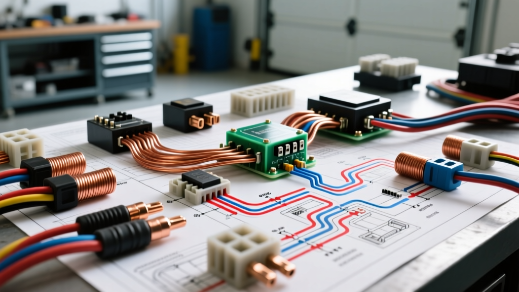
Redefining Hotwire Auto Electrics for Performance and Diagnostics
When master technicians and motorsport engineers discuss hotwire auto electrics, they are rarely referring to the illicit bypassing of steering column immobilizers. In the realm of advanced automotive electrical architecture, a "hotwire" refers to a dedicated, high-current auxiliary circuit designed to bypass restrictive, degraded, or undersized Original Equipment Manufacturer (OEM) wiring harnesses. Whether you are upgrading a fuel delivery system for forced induction, eliminating voltage drop in high-amperage cooling fan circuits, or creating a diagnostic bypass to isolate a failing Powertrain Control Module (PCM) driver, mastering hotwire auto electrics is essential for maintaining optimal system voltage under heavy electrical loads.
Factory wiring harnesses are designed with a focus on cost-reduction and mass assembly, not maximum conductivity. Power often travels from the battery to the under-hood fuse block, through a factory relay, into the cabin to a Body Control Module (BCM), and back out to the engine bay component. This convoluted routing, combined with marginal American Wire Gauge (AWG) sizing and decades of under-hood heat cycling, inevitably leads to severe voltage drop. This guide provides an advanced technical deep dive into designing, sizing, and implementing performance hotwire circuits that restore and exceed OEM electrical efficiency.
The Physics of Factory Voltage Drop
Voltage drop is the enemy of high-performance electrical components. According to Ohm's Law (V = I × R), as resistance (R) increases in a circuit, the voltage (V) available at the load decreases, especially when current draw (I) is high. A fuel pump designed to operate at 13.8V will see a massive reduction in flow rate and pressure if it only receives 11.2V due to harness resistance. Over time, the micro-fretting corrosion inside OEM connector terminals and the work-hardening of copper strands increase resistance exponentially.
Furthermore, the SAE J1128 standard for low-tension primary cable dictates specific strand counts and insulation types. Many OEM manufacturers use Thin-Wall (TWP) or Cross-Linked (GXL) wire that, while space-saving, possesses higher resistance per foot than standard battery cable. When a high-draw component like an electric AC compressor clutch or a brushless fuel pump demands 30+ amps, the factory 14 AWG or 12 AWG wire acts as a resistor, converting wasted electrical energy into heat and starving the component of voltage.
Architecture of a High-Current Hotwire Bypass
The foundation of professional hotwire auto electrics relies on the isolation of the control circuit from the power circuit. We achieve this using heavy-duty, ISO-standard Bosch-style relays. By pulling power directly from the alternator output stud or the main battery positive terminal (via a high-amperage Mega Fuse or ANL fuse), the power circuit is kept as short and thick as possible. The OEM wiring is only used to trigger the relay coil, which draws less than 0.2 amps, completely eliminating voltage drop on the control side.
ISO Mini Relay Pinout and Terminal Specifications
When building a hotwire harness, utilizing a high-quality ISO mini relay (such as those manufactured by Littelfuse or Tyco) is critical. Below is the standard 5-pin configuration and the required wire specifications for a robust hotwire setup.
| Terminal (Pin) | Function | Recommended Wire Gauge | Standard SAE Wire Color | Connection Point |
|---|---|---|---|---|
| 30 | Common (Power In) | 10 AWG or 8 AWG | Red (with inline fuse) | Battery Positive / Alternator B+ Stud |
| 87 | Normally Open (Power Out) | 10 AWG or 8 AWG | Red | Load Component (e.g., Fuel Pump +) |
| 86 | Coil Power (Trigger In) | 14 AWG or 16 AWG | White or Yellow | OEM Relay Output / PCM Driver / Toggle Switch |
| 85 | Coil Ground (Trigger Out) | 14 AWG or 16 AWG | Black | Chassis Ground / Engine Block |
| 87a | Normally Closed (Unused) | N/A | N/A (Insulate/Cut) | Not used in standard hotwire bypass |
Step-by-Step: Building a 40A Fuel Pump Hotwire Circuit
To illustrate the principles of hotwire auto electrics, let us examine the construction of a high-current fuel pump hotwire kit, a common necessity for vehicles upgraded with E85 flex-fuel systems or aftermarket forced induction.
1. Sizing the Power Circuit and Fusing
A dual-pump fuel system can easily pull 35 amps under wide-open throttle. According to Littelfuse automotive relay guidelines, a 40A relay should only be loaded to 80% of its continuous capacity (32A). For a 35A draw, you must step up to a 70A continuous-duty relay or use dual 40A relays in parallel. For the power wire, 8 AWG GXL wire is mandated to keep voltage drop below 0.2V over a standard 10-foot run. Protection is provided by a 50A ANL fuse mounted within 6 inches of the battery terminal.
2. Terminal Crimping and Environmental Sealing
The most common failure point in amateur hotwire kits is poor terminal crimping. Solder-only connections are strictly prohibited in high-vibration automotive environments due to capillary wicking and work-hardening, which leads to brittle fractures. You must use a mil-spec indent crimp tool (such as the Delphi Packard or Molex equivalent) on open-barrel terminals. Following the crimp, seal the connection using adhesive-lined polyolefin heat shrink. The inner thermoplastic adhesive melts and flows into the wire strands, creating a waterproof, oxygen-free seal that prevents green-crust corrosion.
3. Integrating the Trigger Circuit
Locate the factory fuel pump relay in the under-hood fuse block. Identify the wire that provides 12V+ to the fuel pump when the key is in the "Run" or "Crank" position. Splice into this wire using a proper solder-seal butt connector or a Deutsch DT series piggyback terminal. Route this 16 AWG trigger wire to Pin 86 of your new hotwire relay. When the PCM energizes the factory circuit, it simultaneously triggers your heavy-duty hotwire relay, delivering unadulterated battery voltage directly to the pumps.
Advanced Diagnostics: Using Hotwire Logic to Isolate PCM Faults
Beyond performance upgrades, hotwire auto electrics serve as a premier diagnostic tool. Modern vehicles utilize low-side PCM drivers to control relays. If a cooling fan fails to engage, the issue could be a bad motor, a corroded harness, or a fried transistor inside the PCM. By constructing a temporary diagnostic hotwire harness, technicians can perform definitive A/B testing.
Voltage Drop Testing Parameters
When diagnosing the OEM harness against your hotwire bypass, use a digital multimeter (DMM) to measure voltage drop across specific segments while the circuit is under load. A healthy circuit should exhibit minimal resistance.
| Circuit Segment | Maximum Allowable Voltage Drop | Common Failure Mode if Exceeded |
|---|---|---|
| Battery Post to Cable Clamp | 0.05V | Galvanic corrosion, loose torque spec |
| Across OEM Fuse / Fusible Link | 0.10V | Internal fuse fatigue, micro-fractures |
| Across OEM Relay Contacts (30 to 87) | 0.15V | Pitted contact points, carbon buildup |
| Component Ground to Battery Negative | 0.10V | Corroded chassis ground ring terminal |
| Total Hotwire Power Circuit (Battery to Load) | 0.20V | Undersized AWG, poor crimp joints |
If the OEM harness exhibits a 1.5V drop across the factory relay contacts, but your hotwire bypass shows only a 0.05V drop across the new ISO relay, you have conclusively diagnosed internal relay failure without replacing the entire harness. Furthermore, if the PCM control wire drops voltage when placed under the 0.2A load of a relay coil, it indicates a failing PCM driver transistor, a common issue in early 2000s Chrysler and Ford engine management systems.
Best Practices for Grounding High-Current Hotwire Circuits
A hotwire circuit is only as efficient as its ground path. Never ground a high-amperage hotwire circuit to thin sheet metal or painted chassis components. The ground wire should be equal in AWG size to the power wire (e.g., 8 AWG ground for an 8 AWG power feed). Terminate the ground wire using a heavy-duty copper ring terminal, bolted directly to a cleaned, bare-metal location on the engine block or chassis subframe. Apply a dielectric grease over the tightened terminal to prevent electrolysis and moisture intrusion.
Conclusion
Mastering hotwire auto electrics requires a fundamental shift from relying on OEM wiring paradigms to designing purpose-built, physics-compliant electrical architectures. By utilizing heavy-gauge GXL wiring, high-amperage fusing, ISO-standard relays, and mil-spec crimping techniques, you eliminate the voltage drop that robs performance components of their potential. Whether you are supporting a 1000-horsepower fuel system or simply diagnosing a stubborn BCM fault, the principles of the hotwire bypass remain an indispensable tool in the advanced automotive electrician's arsenal. For further reading on primary cable standards and relay load derating, consult the SAE J1128 documentation and Fluke's automotive voltage drop testing guides.