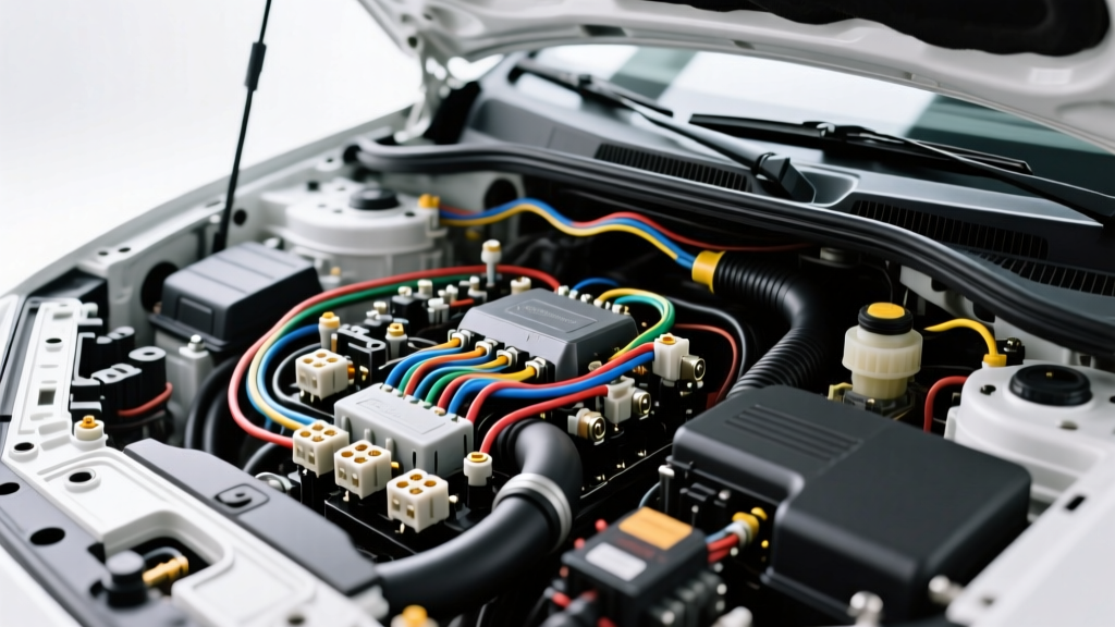
The Evolution of MG Auto Electrics: From Lucas to High-Voltage
Working on MG vehicles requires a deep, dual-discipline understanding of automotive electrical systems. The marque's history spans from the classic, notoriously quirky British Lucas wiring systems of the MGA and MGB eras to the sophisticated, high-voltage (HV) architectures found in modern SAIC-owned EVs like the MG4 and MG ZS EV. When dealing with MG auto electrics, the margin for error is razor-thin. A single wiring mistake on a classic MGB can result in a harness fire, while a procedural oversight on a modern MG EV can lead to lethal electrical shock or catastrophic battery thermal runaway.
This comprehensive guide outlines the most dangerous common mistakes, critical safety warnings, and precise technical specifications required for safely servicing, diagnosing, and upgrading MG electrical systems across all generations.
Classic MG Lucas Wiring: The 'Earth' and Polarity Traps
The foundation of classic MG auto electrics relies on the Lucas color-coded wiring standard and snap-style bullet connectors. The most frequent and destructive mistake enthusiasts make is misunderstanding 'Earth' (ground) polarity and circuit routing. Early MG vehicles (pre-1965) were often Positive Earth, meaning the positive battery terminal was grounded to the chassis. Later models transitioned to Negative Earth. Attempting to jump-start, charge, or wire accessories without verifying the chassis polarity will instantly destroy the Smiths ammeter, reverse the wiper motor, and fry the alternator diodes.
Lucas Wire Color Codes and Circuit Identification
Unlike modern DIN or ISO standards, Lucas relied on a strict base-color and tracer-color system. Misidentifying these leads to short circuits, particularly when integrating modern relays or LED lighting upgrades.
| Base Color | Circuit Function | Typical AWG / mm² | Common Failure Mode |
|---|---|---|---|
| Brown | Unfused Battery Feed (Main Power) | 8 AWG (10mm²) to 2/0 AWG | Chafing at the starter solenoid, causing engine bay fires. |
| White | Fused Ignition Switch Feed | 14 AWG (1.5mm²) | Voltage drop due to corroded ignition switch contacts. |
| Green | Fused Auxiliary (Horn, Wipers) | 14 AWG (1.5mm²) | Overloading the circuit with aftermarket high-draw horns. |
| Blue | Headlamp Circuits | 12 AWG (2.5mm²) | Melting insulation on the dimmer switch due to high-wattage bulbs. |
| Red | Side and Tail Lamps | 16 AWG (1.0mm²) | Brittle PVC insulation cracking near hot SU carburetors. |
| Black | Earth (Ground) Return | Varies | Rusty chassis grounding points causing dim lighting and erratic gauges. |
The SU Fuel Pump Polarity Disaster
A hallmark of classic MG auto electrics is the SU AUA141 or AUA161 electric fuel pump. These pumps rely on an internal set of contact points to pulse the electromagnetic coil. Critical Warning: If you are working on a Negative Earth vehicle and wire the fuel pump backward, or fail to convert it properly during a Negative Earth swap, the internal points will arc violently and burn out within minutes. Always verify the terminal marked 'E' is routed to chassis ground (Negative Earth) or the switched positive feed (Positive Earth), and install a suppression capacitor across the terminals to prevent radio frequency interference (RFI).
Bullet Connector and Ground Strap Upgrades
Standard Lucas bullet connectors (Type A and Type B) are notorious for voltage drop when exposed to moisture. When restoring MG wiring, do not crimp modern vinyl-insulated spade terminals over Lucas wires. Use proper un-insulated brass bullet terminals with dielectric grease. Furthermore, the main engine-to-chassis braided ground strap must be a minimum of 10 AWG (or 6mm²). Upgrading to a high-torque starter motor requires upgrading this ground strap to 4 AWG (25mm²) to prevent current from seeking a ground path through the throttle cable or heater core.
Modern MG EV Architecture: High-Voltage Safety Protocols
Transitioning to modern MG vehicles like the MG4 EV or MG ZS EV introduces entirely different hazards. These vehicles utilize a 400V nominal DC architecture (peaking over 450V under load). The SAE J1673 standard mandates that all high-voltage cabling be shielded and encased in bright orange insulation. However, the presence of orange cables is not the only safety indicator technicians must monitor.
High Voltage Interlock Loop (HVIL) Mistakes
The HVIL is a low-voltage (usually 5V or 12V) safety circuit that runs through all HV connectors. If an orange cable is unplugged or a connector is not fully seated, the HVIL circuit breaks, signaling the Battery Management System (BMS) to instantly open the main contactors. A common, highly dangerous mistake is attempting to 'bypass' a faulty HVIL pin using a jumper wire to clear a BMS isolation fault. Never bypass an HVIL circuit. Doing so defeats the primary safety mechanism designed to prevent lethal arcing if a cable is disconnected under load.
DC-DC Converter and 12V Integration Errors
Modern MG EVs do not have a traditional alternator; they use a DC-DC converter to step down the 400V HV battery to 14.5V for the 12V auxiliary system. The output wiring from the DC-DC converter to the 12V Power Distribution Unit (PDU) typically utilizes heavy-gauge 2 AWG (35mm²) cabling. A frequent mistake is tapping into this 12V DC-DC output line to power high-draw aftermarket accessories (like winches or massive audio amplifiers). The DC-DC converter is usually rated for a maximum continuous output of 1.5kW to 2kW (approx. 100A to 140A). Exceeding this limit will trigger a thermal shutdown of the converter, instantly killing the 12V systems, including the electric power steering and ABS modules, while the vehicle is in motion.
Diagnostic Mistakes: Multimeter Misuse on CAN Bus
Whether diagnosing a late-model MG3 or an MG Cyberster, modern MG auto electrics rely heavily on Controller Area Network (CAN) bus systems for module communication. The CAN-H and CAN-L twisted pair wires operate on differential voltage signals (typically 2.5V to 3.5V).
- The Test Light Mistake: Never use an incandescent test light to probe CAN bus wires. The test light draws excessive current, pulling the bus voltage down and causing immediate module crashes, throwing phantom U-codes (e.g., U0100 - Lost Communication with ECM).
- Low-Impedance Multimeters: Using a cheap, low-impedance digital multimeter (DMM) can load the CAN circuit. Always use a high-impedance DMM (minimum 10 Megohms input impedance) or, preferably, an automotive oscilloscope (like a PicoScope) to view the square wave patterns without interfering with the data stream.
- Terminal Spreading: Backprobing weatherpack connectors with improvised tools like paperclips or sewing needles will spread the delicate female terminal tines. This creates a poor connection that later manifests as an intermittent CAN fault when the vehicle hits a bump. Always use dedicated T-pin backprobes designed for automotive diagnostics.
Lockout/Tagout (LOTO) and PPE Requirements for MG EVs
Before touching any orange cabling on an MG EV, strict Lockout/Tagout procedures must be followed. The MG Car Club UK and official SAIC service manuals dictate the following non-negotiable safety protocol:
- Disconnect the 12V Auxiliary Battery: This removes power to the BMS and HV contactor coils.
- Remove the Manual Service Disconnect (MSD): Located on the HV battery pack, the MSD physically breaks the battery string. Secure it in your pocket (LOTO) to prevent accidental reinstallation.
- Wait for Capacitor Discharge: The Motor Control Unit (MCU) and HVAC compressor inverter contain massive DC bus capacitors. You must wait a minimum of 15 minutes after MSD removal for the bleed resistors to safely discharge these capacitors.
- Verify Zero Voltage: Using a CAT III (1000V) or CAT IV (600V) rated multimeter, test across the HV phases and from Phase to Chassis Ground to confirm 0V.
- Wear Proper PPE: Always wear ASTM D120 Class 0 rubber insulating gloves (rated for 1000V AC / 1500V DC) with leather protectors, and an arc-flash rated face shield when initially verifying voltage.
Torque Specifications: The Hidden Electrical Hazard
Electrical safety is not just about avoiding shock; it is about preventing thermal failures. High-current connections generate immense heat if resistance increases due to loose terminals. When reassembling the HV battery main terminals (typically M10 bolts) on an MG EV, the factory torque specification is strictly 35 to 40 Nm. Under-torquing creates a high-resistance joint that will melt the orange insulation and potentially ignite a fire. Over-torquing can snap the copper terminal stud or crack the battery casing, leading to coolant intrusion and internal short circuits. Always use a calibrated torque wrench and apply the specified dielectric or conductive grease as outlined in the Haynes Auto Manuals or OEM service data.
Conclusion
Navigating MG auto electrics requires respect for both historical quirks and modern high-voltage dangers. Whether you are tracing a parasitic draw through a classic MGB's Lucas harness or diagnosing an isolation fault on an MG4 EV's battery pack, the principles remain the same: verify your polarity, respect the wire gauge limits, use the correct diagnostic impedance, and never compromise on high-voltage safety protocols. By avoiding these common mistakes, you ensure both the longevity of the vehicle's electrical architecture and your own personal safety.