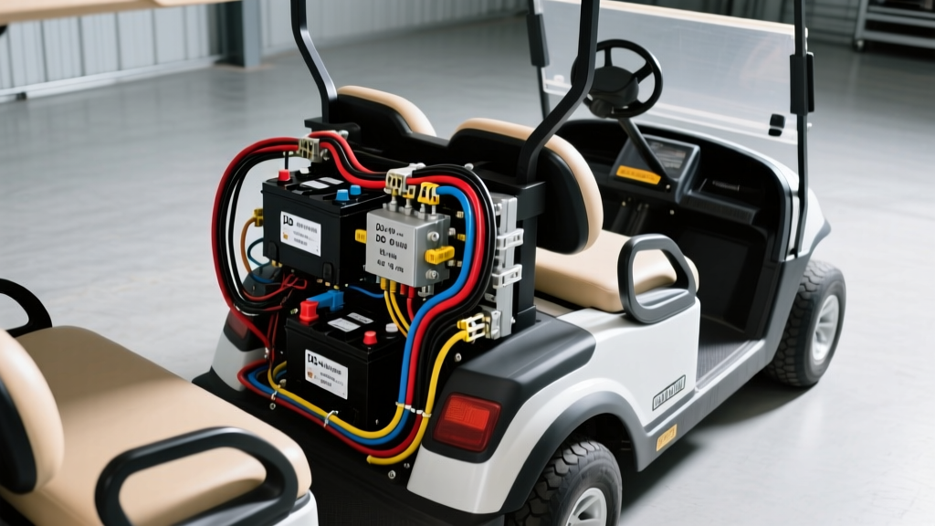
Understanding the 2021 Club Car Onward Lifted 4 Passenger Electric Platform
When you take delivery of a 2021 Club Car Onward lifted 4 passenger electric model, you are looking at one of the most versatile platforms in the personal electric vehicle market. However, adding a 6-inch lift kit, 23-inch off-road tires, and a rear-facing seat fundamentally alters the electrical demands placed on the factory 48V system. For beginners and DIY enthusiasts, understanding the baseline wiring architecture is critical before adding LED light bars, sound systems, or upgraded controllers. This guide breaks down the essential wiring fundamentals, from the main battery pack to the DC-DC converter, ensuring your build remains safe, reliable, and capable of handling the extra weight.
Core 48V Architecture and the AC Controller
The 2021 and newer Onward platform utilizes an Excel AC motor paired with a sophisticated AC motor speed controller. Unlike older DC series-wound motors that rely on carbon brushes, the AC system uses a 3-phase power delivery and a delicate hall-sensor feedback loop to monitor rotor position. This means the wiring harness is split into two distinct domains: the high-current 3-phase motor drive and the low-voltage logic/sensor circuits.
Main Power and Solenoid Circuit
The main high-current circuit flows from the battery pack positive terminal to the heavy-duty main solenoid (typically an Albright SW80 or equivalent 400A continuous duty relay), and then into the controller B+ terminal.
- Main Cables: Factory wiring often uses 4 AWG copper. On a lifted 4-passenger build, the increased rolling resistance and rotational mass of larger tires cause the motor to draw higher amperage during initial acceleration and hill climbs.
- The Pre-Charge Resistor: Connected across the solenoid large terminals, this 250-ohm, 2-watt resistor is vital. It slowly charges the controller internal capacitors before the main solenoid engages. Failure Mode: Beginners often bypass or ignore a melted pre-charge resistor. Without it, the massive inrush current will arc and weld the main solenoid contacts shut, causing a runaway cart.
- Motor Phase Cables: The 3-phase cables (typically Yellow, Green, and Blue) connect the controller U, V, and W terminals to the motor. These must be torqued to exactly 15 ft-lbs to prevent heat buildup and phase-shorting.
Upgrading Wire Gauge for Lifted Applications
According to SAE J1128 Low Tension Cable Standards, wire ampacity is heavily dependent on ambient temperature and bundling. Because a lifted cart frequently operates at high current (150A to 250A peak) on inclines, voltage drop becomes a severe issue. If the voltage at the controller drops below 42V under load, the cart will trigger a low-voltage rollback or limp mode.
| Circuit Segment | Factory AWG | Upgraded AWG | Reason for Upgrade |
|---|---|---|---|
| Battery Pack to Solenoid | 4 AWG | 1/0 AWG | Reduces voltage drop during heavy acceleration with 23-inch tires. |
| Solenoid to Controller B+ | 4 AWG | 1/0 AWG | Prevents terminal melting at high continuous amp draw. |
| Controller to Motor (Phases) | 6 AWG | 4 AWG | Lowers resistance and heat in the 3-phase AC drive lines. |
| Controller to Frame Ground | 8 AWG | 4 AWG | Ensures clean logic ground reference for sensitive hall sensors. |
Pro Tip: Always use pure copper, fine-strand welding cable for main power upgrades. Avoid copper-clad aluminum (CCA) wires sold in cheap automotive kits, as they have higher resistance and are prone to snapping under chassis vibration. Refer to Club Car Official Service Manuals for specific routing diagrams to avoid sharp chassis edges.
The DC-DC Converter: 12V Accessory Fundamentals
To power headlights, taillights, and a horn without tapping into a single 8V battery (which causes severe pack imbalance and ruins lead-acid cells), the Onward uses a 48V-to-12V DC-DC step-down converter. On a lifted build, owners frequently add roof-mounted LED light bars and underbody neon, which can easily exceed the factory 15-amp converter limit.
Wiring the Accessory Bus Safely
- Locate the Converter: Usually mounted under the passenger dash or near the battery compartment. It features heavy 48V input wires (Red/Black, 10 AWG) and 12V output wires (Yellow/Black, 12 AWG).
- Install a Relay Harness: Never wire high-draw LED light bars directly to the factory toggle switch. Use a standard 12V automotive 4-pin relay (30A). Wire the relay coil to the factory switch, and run the relay switched power directly from the DC-DC converter 12V output, protected by an inline 20A ATC fuse.
- Grounding: Do not rely on the aluminum chassis for high-current 12V grounds. Run a dedicated 10 AWG ground wire from your accessory bus back to the DC-DC converter negative terminal or a dedicated stainless steel ground bus bar.
Forward/Reverse (F/R) Microswitch Wiring
The F/R switch on the 2021 Onward does not route main motor power; it simply sends a low-voltage logic signal to the AC controller via a 16-pin Molex connector. The microswitches are located under the driver seat near the motor.
- Forward Signal: Typically utilizes a Blue/White tracer wire (18 AWG) completing the circuit to Controller Pin 4.
- Reverse Signal: Typically utilizes a Green/White tracer wire (18 AWG) completing the circuit to Controller Pin 5.
- Common Ground: Black wire (18 AWG) tied to the logic ground.
Beginner Mistake: If your cart only moves in forward but not reverse, do not immediately suspect the controller. 90% of the time, the reverse microswitch is misaligned. The physical cam on the F/R lever must depress the switch plunger fully. Adjust the 10mm mounting nuts to ensure a distinct click when shifted.
Troubleshooting Common Onward Wiring Faults
Use this decision tree to diagnose common electrical gremlins found in modified, lifted Onward carts:
Symptom: Cart Stutters or Cuts Out on Hills
- Cause 1: Voltage drop due to undersized main cables. Fix: Upgrade to 1/0 AWG pure copper cables and apply dielectric grease to all lugs.
- Cause 2: Loose battery terminal nuts. Fix: Torque all 5/16-inch battery terminal nuts to exactly 110 in-lbs. Over-tightening strips the lead threads; under-tightening causes arcing.
Symptom: Solenoid Clicks Rapidly But Cart Will Not Move
- Cause 1: Failing pre-charge resistor. Fix: Test the 250-ohm resistor with a multimeter. Replace if open.
- Cause 2: Throttle box failure. The inductive throttle sensor may be out of the 0-5V range. Fix: Backprobe the throttle signal wire (Green, 18 AWG) at the controller. It should read 0.8V at rest and smoothly sweep to 3.4V at full depression.
Symptom: 12V Accessories Flicker or DC-DC Converter Gets Hot
- Cause 1: Overloaded converter. Fix: Calculate total 12V draw. If exceeding 15A, upgrade to a 30A or 50A aftermarket DC-DC converter (e.g., LED Headlights draw ~3A, but a roof light bar can draw 12A+).
- Cause 2: Corroded 48V input terminals on the converter. Fix: Clean with a wire brush and seal with liquid electrical tape to prevent moisture ingress from lifted wheel wells.
Final Thoughts for the DIY Builder
Wiring a 2021 Club Car Onward lifted 4 passenger electric cart is highly rewarding, but it requires respect for the high amperage involved in a 48V AC system. By upgrading your main power cables to handle the extra rotational mass of a lift kit, properly fusing your 12V accessory bus, and understanding the logic signals that govern the AC controller, you will build a vehicle that is not only visually aggressive but electrically bulletproof. For further community-driven wiring diagrams and harness pinouts, the Buggies Gone Wild Electrical Archives remain an invaluable resource for cross-referencing factory harness colors against aftermarket controller installations.