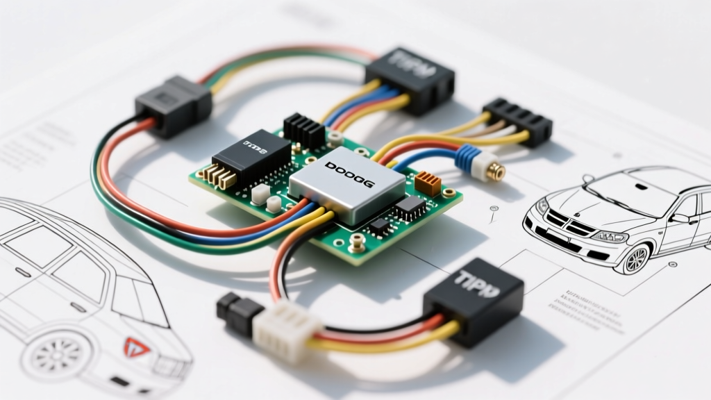
The TIPM: Ground Zero for Dodge Journey Electrical Problems
When enthusiasts tackle an upgrade or modification project on a 2009-2020 Dodge Journey—whether installing a high-output audio amplifier, a heavy-duty winch, or an LED light bar—they frequently awaken dormant electrical gremlins. The root cause of many dodge journey electrical problems during these projects traces back to the Totally Integrated Power Module (TIPM). Unlike traditional fuse boxes, the TIPM is a multiplexed power distribution center containing internal micro-relays, solid-state switches, and a dedicated logic board that communicates directly with the Body Control Module (BCM) via the CAN bus network.
Factory circuits are engineered with strict current thresholds. When you tap into an OEM circuit to trigger a 30A aftermarket relay, the inrush current and voltage backfeed can confuse the TIPM's internal smart switches, triggering a fail-safe shutdown. Understanding how to bypass, isolate, and properly ground your modifications is critical to completing your upgrade project without permanently bricking the vehicle's power distribution architecture.
Why Aftermarket Upgrades Trigger TIPM Failures
The TIPM monitors current draw on every output circuit. If you wire a 55W LED light bar directly to the OEM headlight trigger wire, the TIPM detects an abnormal resistance and current profile compared to the factory halogen bulbs. According to SAE J1113 standards for vehicular electromagnetic compatibility and circuit protection, the module will interpret this variance as a short circuit or bulb outage, rapidly cycling the power (flickering) or shutting the circuit down entirely to protect the internal PCB traces.
Diagnostic Decision Tree: Mod-Induced Electrical Gremlins
Before ripping apart your dashboard, use this symptom-cause-fix decision tree to isolate modification-induced faults.
- Symptom: Fuel pump primes, but engine cranks without starting immediately after installing a high-draw audio amplifier.
- Cause: Voltage drop on the main battery feed caused the TIPM internal fuel pump micro-relay to starve and drop offline. The internal solder joints on Journey TIPMs are notorious for fracturing under thermal and electrical stress.
- Fix: Perform an external fuel pump relay bypass (detailed below) and upgrade the main alternator charge wire.
- Symptom: Headlights and dash illumination flicker violently when the winch solenoid or air compressor engages.
- Cause: High-amperage inrush creates a massive voltage spike on the chassis ground, backfeeding into the low-speed CAN bus (I-Bus) and causing BCM logic resets.
- Fix: Install a dedicated 1/0 AWG ground strap from the engine block to the chassis, and use a TVS (Transient Voltage Suppression) diode across the winch contactor coil.
- Symptom: Aftermarket LED tail lights hyper-flash or trigger a 'Bulb Out' warning on the EVIC display.
- Cause: The TIPM's pulse-width modulation (PWM) diagnostic checks detect the low current draw of the LEDs.
- Fix: Install inline CAN bus decoders with integrated load resistors, or reflash the BCM via a specialized OBD2 tuning tool to disable bulb-out diagnostics for those specific circuits.
The Hardwire Bypass: Upgrading the Fuel Pump Circuit
The most infamous of all dodge journey electrical problems is the internal fuel pump relay failure. Because the relay is soldered directly to the TIPM circuit board, dealerships typically require you to replace the entire $1,200 module. For a modification project, installing an external hardwire bypass is a superior, more reliable upgrade that ensures your fuel system receives consistent voltage regardless of TIPM health.
Step-by-Step External Relay Bypass Wiring
- Locate the Trigger and Feed Wires: Access the TIPM under the hood. You will need to tap into Connector C5 and Connector C6. Use a Metri-Pack 280 terminal extraction tool to safely access the wires without piercing the insulation, which invites corrosion.
- Identify the Fuel Pump Feed: At Connector C5, locate Pin 14. This is a Dark Green/White wire. This is the OEM output from the failed internal relay to the fuel pump.
- Identify the Ignition Trigger: At Connector C6, locate Pin 18. This is a Pink/White wire (Fused Ignition Output - Run/Start). This will serve as the trigger signal for your new external relay.
- Wire the 30A Bosch-Style Relay:
- Pin 30 (Battery Feed): Run a new 10 AWG wire directly from the positive battery terminal, protected by an inline 20A ATO fuse positioned within 6 inches of the battery.
- Pin 87 (Normally Open Output): Splice this 10 AWG wire directly into the Dark Green/White wire (C5, Pin 14) leading to the fuel pump.
- Pin 86 (Coil Ground): Secure a 14 AWG wire to a clean, unpainted chassis ground. Verify continuity to the battery negative terminal using a multimeter (must read less than 0.5 ohms).
- Pin 85 (Coil Trigger): Connect a 14 AWG wire to the Pink/White ignition trigger wire (C6, Pin 18) using a Mopar-approved butt connector with heat shrink adhesive.
- Test and Secure: Turn the ignition to the 'RUN' position. You should hear the external relay click, and the fuel pump should prime for exactly 2 seconds before the PCM cuts the trigger signal. Zip-tie the relay high on the firewall to prevent water ingestion.
Grounding Upgrades: Eliminating CAN Bus Flicker
When upgrading the Dodge Journey's electrical system for high-draw accessories, the factory grounding infrastructure is often the weakest link. The factory ground straps are prone to galvanic corrosion, especially in regions that use road salt. A poor ground forces return current to seek alternative paths through the CAN bus shielding or sensor grounds, leading to erratic module behavior.
Voltage Drop Testing the Factory Grounds
Before adding new accessories, validate the existing grounds using a Fluke 87V digital multimeter set to DC millivolts (mV). Place the red probe on the battery negative post and the black probe on the ground lug you are testing. Have an assistant crank the engine. According to AA1Car diagnostic guidelines, a healthy ground circuit should exhibit a voltage drop of less than 50mV (0.050V) during cranking. If your reading exceeds 100mV, the ground point must be cleaned or upgraded.
Journey Ground Point Specification Chart
| Ground ID | Location | Factory Wire Gauge | Upgrade Recommendation | Torque Spec |
|---|---|---|---|---|
| G100 | Battery to Left Strut Tower | 4 AWG | Upgrade to 1/0 AWG flexible welding cable | 12 Nm (106 in-lbs) |
| G104 | Engine Block to Passenger Frame Rail | 6 AWG | Add secondary 2 AWG strap for audio amps | 15 Nm (133 in-lbs) |
| G200 | Left Dash / BCM Ground | 14 AWG | Clean contact surface; apply dielectric grease | 8 Nm (71 in-lbs) |
| G305 | Rear Hatch / Liftgate Modules | 16 AWG | Upgrade to 12 AWG to fix rear wiper/wiper faults | 6 Nm (53 in-lbs) |
CAN Bus Decoders and LED Lighting Mods
Upgrading exterior lighting is a staple modification project, but the Journey's BCM actively monitors the PWM feedback loop of the exterior lighting circuits. If you install standard LED replacement bulbs in the turn signals or brake lights, the TIPM will interpret the low resistance as a blown bulb.
To solve this without cutting into the OEM harness, use plug-and-play CAN bus decoders that feature integrated gold-film load resistors. These decoders mimic the exact 2.1A current draw of a standard 3157 incandescent bulb. When wiring custom LED rock lights or off-road pods, never tap into the OEM parking light circuit for the trigger. Instead, use an add-a-fuse tap in the cabin Integrated Power Module (IPM) on a fused accessory circuit (e.g., the 12V power outlet fuse), ensuring your aftermarket lighting operates entirely outside the TIPM's multiplexed exterior lighting logic.
Final Verification and System Reset
After completing any hardwire bypass, grounding upgrade, or CAN bus decoder installation, you must reset the vehicle's logic modules to clear phantom fault codes. Disconnect the negative battery terminal (G100) for 15 minutes to allow the TIPM and BCM capacitors to fully discharge. Upon reconnection, perform the PCM idle relearn procedure by turning the ignition to the 'RUN' position without starting the engine for 30 seconds, then start the engine and let it idle in park with all accessories off for 5 minutes. This ensures the new electrical baseline is recognized by the network, securing your modification project against future electrical gremlins.