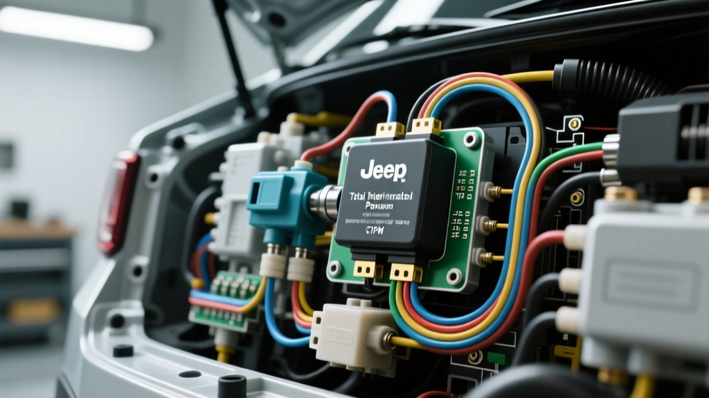
Resolving Jeep Compass Electrical Problems: The TIPM Fuel Pump Bypass Installation
Owners of the 2007-2016 MK platform vehicles frequently encounter severe Jeep Compass electrical problems, with the most notorious being sudden engine stalling, crank-no-start conditions, and intermittent fuel pump failures. In the vast majority of these cases, the root cause is not a failed fuel pump or a bad ignition switch, but rather a micro-fracture in the printed circuit board (PCB) solder joints inside the Totally Integrated Power Module (TIPM). The TIPM acts as the central nervous system for the vehicle's electrical distribution, housing internal relays that are not designed to be serviced or replaced individually by the manufacturer.
When the internal fuel pump relay solder joints crack due to years of thermal cycling and high-current vibration, the fuel pump loses its 12V feed. While dealerships often recommend a complete $1,200+ TIPM replacement, automotive electrical experts utilize a much more reliable and cost-effective solution: installing an external TIPM bypass relay kit. This practical how-to installation guide will walk you through systematically diagnosing the fault and installing an external heavy-duty relay to permanently bypass the failed internal circuitry.
Phase 1: Diagnostic Verification Before Installation
Before cutting into any wiring, you must definitively prove that the TIPM is the source of the Jeep Compass electrical problems and not a seized fuel pump or a corroded rear ground. Jumping straight to installation without testing violates core troubleshooting principles.
Testing at the Rear Fuel Pump Connector (C302)
- Access the fuel pump module connector (C302) located under the rear passenger seat or via the cargo area access panel, depending on your specific model year.
- Set your Digital Multimeter (DMM) to DC Volts.
- Connect the black probe to a verified, clean chassis ground and the red probe to the Dark Green/Red wire (Pin 1) on the harness side of C302. This is the 12V feed from the TIPM.
- Turn the ignition to the RUN position. You should see a 12V reference for exactly 2 to 3 seconds as the TIPM primes the system. If you read 0V, the TIPM is failing to output power.
- Next, test the ground circuit. Switch your DMM to Ohms and measure continuity between Pin 2 (Black wire) and the chassis. You should read less than 0.5 ohms.
If the ground is solid but the switched 12V feed is missing during the prime cycle, you have confirmed an internal TIPM relay failure. According to data logged in the NHTSA Vehicle Safety Database, this specific PCB fracture accounts for a massive percentage of MK-platform stall complaints.
Phase 2: Wiring Specifications and Component Sourcing
To perform this installation correctly, you must abandon cheap 'scotch-lock' T-taps which cause high resistance and future corrosion. We will use solder-seal heat shrink connectors and automotive-grade GXL wire. The external relay must be a standard Bosch-style 4-pin Mini ISO relay capable of handling continuous 20A+ loads, such as those outlined in Littelfuse Automotive Relay Specifications.
TIPM C1 Connector Pinout and Wiring Chart
| Circuit Function | TIPM C1 Pin | Factory Wire Color | Bypass Wire AWG | Relay Terminal |
|---|---|---|---|---|
| Constant 12V Battery Feed | Pin 1 | Red / White | 14 AWG GXL | Pin 30 (Input) |
| Ignition Run/Start Trigger | Pin 12 | Dark Green / White | 18 AWG GXL | Pin 86 (Coil +) |
| Fuel Pump Power Output | Pin 35 | Dark Green / Red | 14 AWG GXL | Pin 87 (Output) |
| Relay Coil Ground | N/A (Chassis) | Black | 14 AWG GXL | Pin 85 (Coil -) |
Note: Always install an inline 20A ATO blade fuse on the new 14 AWG constant 12V feed (Pin 30) within 6 inches of the tap point to protect the circuit.
Phase 3: Step-by-Step Bypass Installation Guide
Step 1: Safety and TIPM Access
Disconnect the negative battery terminal and isolate it. Unlatch the TIPM cover located in the driver's side engine bay. Release the locking tab on the bottom of the TIPM and slide the unit upward to expose the underside harness connectors. Locate the large 32-way C1 connector (usually the gray or black connector closest to the firewall). Depress the locking lever and unplug C1.
Step 2: Tapping the Trigger and Power Circuits
We need to extract a switched 12V signal to tell our external relay when to close. Using a terminal removal tool, carefully extract Pin 12 (Dark Green/White) from the C1 connector. Strip a small section of the wire, solder your 18 AWG trigger wire using a parallel splice (Western Union splice), and seal it with adhesive-lined heat shrink. Re-insert the Pin 12 terminal back into the C1 connector until it clicks. Repeat this exact solder-and-seal process for Pin 1 (Red/White) using your 14 AWG constant power wire. Remember to slide your 20A inline fuse holder onto this 14 AWG wire before terminating it to Relay Pin 30.
Step 3: Bypassing the Failed Internal Output
Now we must intercept the fuel pump feed. Extract Pin 35 (Dark Green/Red) from the C1 connector. This wire originally carried power from the internal relay to the fuel pump. Cut the factory wire approximately 2 inches from the connector. Strip both ends. Solder your new 14 AWG wire (coming from Relay Pin 87) to the harness side of the cut Dark Green/Red wire. This ensures your external relay now directly feeds the rear fuel pump. Cap off the 2-inch stub remaining on the C1 connector terminal with a sealed heat shrink end-cap to prevent moisture ingress back into the TIPM.
Step 4: Grounding and Relay Mounting
Crimp a high-quality ring terminal to your 14 AWG Black ground wire (connected to Relay Pin 85). Locate a clean, unpainted metal surface on the driver's side strut tower or inner fender. Sand away any paint or corrosion, attach the ground ring terminal, and secure it with a stainless steel bolt and star washer to ensure a low-resistance path. Mount the external Mini ISO relay in a protective plastic housing and zip-tie it securely to the existing factory wiring harness loom near the TIPM, ensuring it is shielded from direct water spray and excessive exhaust heat.
Phase 4: Verification and Voltage Drop Testing
Reconnect the negative battery terminal. Before starting the vehicle, we must validate the installation against SAE J1141 Electrical Wiring Standards, which dictate strict maximum allowable voltage drops for automotive power circuits.
- Set your DMM to DC Volts.
- Place the red probe on the positive battery terminal and the black probe on the newly spliced Dark Green/Red fuel pump feed wire near the TIPM.
- Turn the key to RUN. The external relay should audibly click, and the fuel pump should prime.
- Read the DMM. A properly soldered, correctly sized 14 AWG circuit should show a voltage drop of less than 0.2V on the power side. If you read 0.5V or higher, you have a high-resistance connection (likely a cold solder joint or a poor crimp) that must be redone.
- Perform the same test on the ground side (Red probe on the fuel pump ground wire at C302, black probe on the negative battery terminal). The ground side voltage drop must also be under 0.2V.
Summary of the Fix
By installing this external relay, you have entirely removed the high-current fuel pump load from the fragile, aging internal PCB of the TIPM. The internal relay may still click uselessly, but the actual heavy lifting is now being handled by a robust, easily replaceable external Mini ISO relay. This permanent fix eliminates the most dangerous of all Jeep Compass electrical problems, restoring reliable fuel delivery and ensuring your vehicle starts on command every single time.