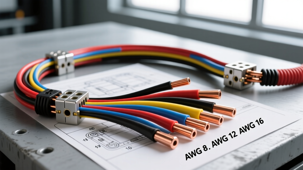
When engineering electrical architectures for Class 8 commercial trucks, military tactical vehicles, and large marine vessels, selecting the correct wire gauge for 24V DC systems is critical for operational reliability. Unlike standard 12V passenger vehicles, 24V DC platforms—such as the Freightliner Cascadia, Peterbilt 389, and military HMMWV fleets—operate under entirely different thermal and electrical constraints. This technical specification reference provides automotive and heavy-duty electricians with the precise AWG sizing matrices, voltage drop calculations, and SAE compliance standards required for 24V DC applications.
The Amperage Advantage: 24V DC vs. 12V DC Architectures
The fundamental advantage of a 24V DC electrical system lies in Joule's heating law and the power equation (P = I × V). By doubling the system voltage from 12V to 24V, the current (amperage) required to deliver the same wattage is halved. This reduction in current draw drastically alters the wire gauge for 24V DC requirements, allowing engineers to utilize smaller, lighter, and more flexible AWG conductors while maintaining identical power delivery.
For example, a heavy-duty diesel cab heater rated at 1,200W will draw 100 amps on a 12V system, mandating a minimum of 4 AWG wire for a 10-foot run to prevent excessive voltage drop and thermal degradation. On a 24V DC architecture, that same 1,200W heater draws only 50 amps. Consequently, an 8 AWG primary cable is entirely sufficient, reducing harness weight and copper costs while improving routing flexibility through the vehicle's bulkhead.
Technical Specification Matrix: AWG Sizing for 24V DC Loads
The following matrix outlines the recommended American Wire Gauge (AWG) sizing for common 24V DC heavy-duty loads. These specifications assume a maximum ambient temperature of 105°C (221°F) and utilize SAE J1128 Type HDT or cross-linked polyethylene (XLPE) insulated conductors. Always calculate based on the continuous amperage draw, not the peak surge, unless the load is strictly momentary (e.g., starter solenoids).
| Load Application | Wattage (W) | Current @ 24V (A) | AWG (0-10 ft Run) | AWG (10-20 ft Run) |
|---|---|---|---|---|
| LED Marker/ Clearance Lamps (Set) | 60W | 2.5A | 16 AWG | 14 AWG |
| Heavy-Duty Cab Blower Motor | 240W | 10A | 12 AWG | 10 AWG |
| Electric Engine Block Heater | 1000W | 41.6A | 8 AWG | 6 AWG |
| Hydraulic PTO Solenoid Pack | 480W | 20A | 10 AWG | 8 AWG |
| APU (Auxiliary Power Unit) Inverter Feed | 3000W | 125A | 1/0 AWG | 2/0 AWG |
| NATO Slave Receptacle (STANAG 4074) | N/A | 1000A (Peak) | 2/0 AWG | 4/0 AWG |
Voltage Drop Calculations and SAE Compliance
In 24V DC systems, voltage drop remains a primary cause of electronic control module (ECM) faults and premature actuator failure. According to ABYC E-11 standards and general heavy-duty engineering practices, voltage drop should not exceed 3% (0.72V) for critical electronics and ECM power feeds, and no more than 5% (1.2V) for general resistive loads like lighting and heating elements.
The formula for calculating voltage drop in a single-phase DC circuit is: VD = (2 × L × I × R) / 1000, where L is the total loop length in feet, I is the current in amps, and R is the conductor resistance per 1,000 feet at the operating temperature.
Maximum Cable Run Lengths at 3% Voltage Drop (0.72V)
Use the table below to determine the maximum one-way cable run length before upsizing your wire gauge for 24V DC circuits. This data is critical when routing harnesses from the battery box to the rear chassis of extended-wheelbase commercial trucks.
| Wire Gauge (AWG) | Max Continuous Amps | Max Length (ft) @ 10A | Max Length (ft) @ 50A | Max Length (ft) @ 100A |
|---|---|---|---|---|
| 14 AWG | 15A | 36 ft | N/A | N/A |
| 12 AWG | 20A | 58 ft | 11 ft | N/A |
| 10 AWG | 30A | 92 ft | 18 ft | N/A |
| 8 AWG | 45A | 146 ft | 29 ft | 14 ft |
| 4 AWG | 85A | 370 ft | 74 ft | 37 ft |
| 1/0 AWG | 150A | 735 ft | 147 ft | 73 ft |
Insulation Standards and Termination Protocols
Selecting the correct wire gauge for 24V DC is only half the engineering battle; insulation chemistry and termination methods dictate long-term harness survival in high-vibration, high-heat environments. Standard PVC-insulated wire (Type GPT) is generally insufficient for Class 8 engine bays. Instead, specify SAE J1128 Type HDT or SXL (Cross-Linked Polyethylene) cables. SXL insulation withstands continuous temperatures up to 125°C (257°F) and offers superior resistance to diesel fuel, DEF (Diesel Exhaust Fluid), and abrasive chassis vibration.
For military and severe-duty applications, harnesses must comply with MIL-STD-1275D transient voltage requirements, necessitating heavy-duty braided shielding and MIL-spec heat shrink tubing with adhesive-lined interiors to prevent capillary moisture wicking.
Connector and Crimp Specifications
- Terminals: Use tinned copper ring terminals with a brazed seam to prevent splitting under high-torque stud tightening (e.g., 10-12 lb-ft on standard 3/8" battery studs).
- Crimping: Never use solder on heavy-gauge 24V battery cables. Solder creates a rigid stress point that will fatigue and snap under chassis flex. Utilize MIL-DTL-22520 compliant pneumatic indent crimpers for all AWG 10 and larger terminations.
- Color Coding: While SAE standardizes Red for positive and Black for negative, many 24V heavy-duty OEMs utilize Red with a White tracer (Red/White) to designate 24V switched ignition circuits, differentiating them from constant 24V battery feeds.
Real-World Troubleshooting: 24V Heavy-Duty Failure Modes
When diagnosing 24V DC electrical faults, technicians frequently misattribute component failure to the load itself, when the root cause is an undersized wire gauge or poor termination. Below are common failure modes specific to 24V commercial architectures:
1. Alternator Sense Wire Voltage Drop
In systems utilizing high-output alternators (e.g., Delco Remy 40SI or Leece-Neville 4600 series), the ECM or internal regulator relies on a dedicated "sense" wire to monitor voltage at the battery bank. If this 14 AWG or 12 AWG sense wire is undersized, corroded, or spliced improperly, it will experience a voltage drop. The alternator will falsely read low system voltage and compensate by overcharging the 24V system (pushing 30V+). This leads to boiling electrolyte in the series-linked 12V batteries and catastrophic ECM failure.
2. Starter Motor Voltage Drop & SAE J2128 Compliance
24V starter motors on heavy diesel engines (e.g., Cummins ISX15, Detroit DD15) require immense cranking amperage, often exceeding 1,000A for several seconds. The SAE J2128 standard dictates the use of SGT (Starter Gauge Cable) or fine-strand welding cable for flexibility. A common diagnostic error is measuring voltage drop at the battery terminals rather than directly at the starter solenoid stud during a crank event. A healthy 24V starting circuit should maintain a minimum of 22V at the starter solenoid during cranking. If voltage drops below 20V, the issue is almost always undersized battery cables, corroded frame ground straps, or failing series-parallel battery bank interconnects.
3. Galvanic Corrosion at Bi-Metallic Junctions
24V systems operating in marine or winter-salted environments are highly susceptible to galvanic corrosion, particularly where copper cables meet aluminum chassis grounds or brass bus bars. This corrosion introduces massive resistance, effectively reducing the functional wire gauge and causing localized heat melting. Always apply anhydrous dielectric grease or NO-OX-ID "A-Special" compound to all 24V ground studs and high-current lugs.
4. Inrush Current Tripping Magnetic Breakers
Unlike thermal breakers, magnetic circuit breakers trip instantaneously based on current spikes. 24V DC motors (like APU compressors or liftgate solenoids) can experience inrush currents up to 600% of their continuous draw for the first 200 milliseconds. If the wire gauge is sized strictly to the continuous draw without accounting for the breaker's trip curve, nuisance tripping will occur. Always pair 24V motor circuits with hydraulic-magnetic breakers featuring an inrush delay curve.