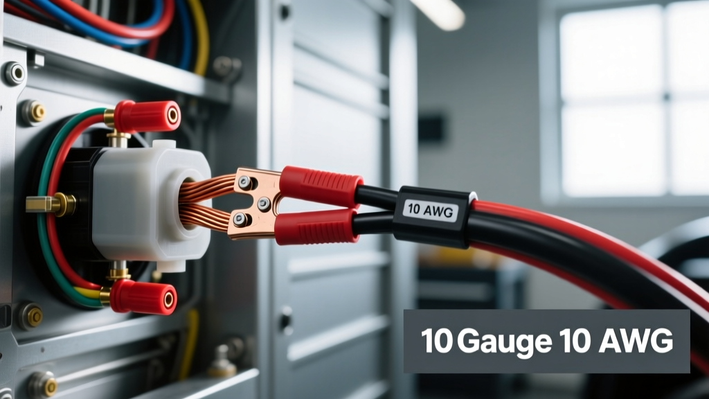
The Core Question: How Many Amps Will a 10 Gauge Wire Carry?
When designing or repairing high-draw automotive circuits, the most common question we receive at the bench is: how many amps will a 10 gauge wire carry? The short answer for automotive chassis wiring is 30 Amps continuously. However, the complete answer requires understanding the difference between building wire standards and automotive wire standards, as well as calculating voltage drop over distance.
In automotive applications, we do not use the National Electrical Code (NEC) standards designed for household AC wiring. Instead, we rely on SAE J1128 specifications. Automotive 10 AWG wire features highly stranded copper (typically 105 to 259 strands depending on flexibility requirements) and high-temperature insulation like GXL (125°C) or TXL (150°C). Because automotive wire is rated for higher ambient temperatures and utilizes thinner, more heat-resistant insulation, its ampacity ratings differ significantly from standard copper THHN building wire.
SAE vs. NEC: Automotive Ampacity Standards
To understand why 10 AWG is rated for 30A in a vehicle but might be derated in a residential conduit, we must look at the chassis wiring ampacity chart. In a vehicle, wires are often routed in free air or in small, heat-shielded bundles, allowing for better heat dissipation than a packed residential wall cavity.
| AWG Size | SAE Automotive Ampacity (Chassis) | NEC Ampacity (Building/Conduit) | Max Fuse/Breaker Size (Auto) |
|---|---|---|---|
| 8 AWG | 50 Amps | 40 Amps | 50A |
| 10 AWG | 30 Amps | 30 Amps | 30A |
| 12 AWG | 20 Amps | 20 Amps | 20A |
| 14 AWG | 15 Amps | 15 Amps | 15A |
Note: Ampacity assumes a 12V-14V DC system. Always size your inline fuses or circuit breakers to protect the wire, not the load. A 10 AWG wire should never be protected by a fuse larger than 30A.
Complete Wiring Diagram Walkthrough: High-Draw EFI Fuel Pump
To see how this ampacity rule applies in the real world, let us walk through a complete wiring diagram for a high-performance EFI fuel pump (such as a Walbro 450lph or Aeromotive 340). These pumps are notorious for drawing massive current, especially at higher fuel pressures.
At 40 PSI (base pressure), a 450lph pump might draw 15 Amps. However, at 80+ PSI (common in boosted applications with a 1:1 fuel pressure regulator), the current draw spikes to 22 to 25 Amps. While a 12 AWG wire is technically rated for 20 Amps, using it for a 25-Amp load will result in catastrophic voltage drop, melted insulation, and fuel starvation under wide-open throttle (WOT). This is exactly why 10 AWG wire is the mandatory minimum for the main power and ground feeds in this diagram.
Component Breakdown & Wire Sizing
- Power Feed (Battery to Relay): 10 AWG Red SAE GXL wire. Capable of carrying the 30A peak surge without exceeding temperature thresholds.
- Load Feed (Relay to Pump): 10 AWG Red/Blue tracer wire. Maintains critical voltage at the pump hanger.
- Ground Return (Pump to Chassis): 10 AWG Black wire. Often overlooked; a poor ground creates the same voltage drop as an undersized power wire.
- Trigger Circuit (ECU to Relay): 18 AWG wire. The relay coil draws less than 0.2 Amps, so heavy gauge wire is unnecessary here.
Bosch-Style 5-Pin Relay Pinout Specifications
For this walkthrough, we are using a heavy-duty Bosch-style 5-pin relay housed in a weather-sealed connector. The pin numbering is standardized across the industry.
| Relay Pin | Function | Wire Gauge | Wire Color | Destination |
|---|---|---|---|---|
| Pin 30 | Constant 12V+ Input | 10 AWG | Red | Battery Positive (via 30A Maxi Fuse) |
| Pin 87 | Switched 12V+ Output | 10 AWG | Red/Blue | Fuel Pump Positive Terminal |
| Pin 85 | Relay Coil Ground | 14 AWG | Black | Clean Chassis Ground |
| Pin 86 | Trigger Signal Input | 18 AWG | Yellow | ECU Fuel Pump Relay Output / Inertia Switch |
| Pin 87a | Normally Closed (NC) | N/A | N/A | Not used in standard fuel pump circuits (cut/heatshrink) |
Voltage Drop Calculations for 10 AWG
Knowing how many amps a 10 gauge wire will carry is only half the battle; the other half is voltage drop. High-draw fuel pumps require a minimum of 13.5V at the terminals to achieve their published flow rates. If voltage drops below 12V, the pump slows down, and your engine runs lean under boost.
The formula for DC voltage drop is: VD = (2 x L x I x R) / 1000
- L = Length of the wire in feet (round trip, so multiply one-way distance by 2)
- I = Current in Amps (25A for our WOT scenario)
- R = Resistance per 1,000 feet of wire
According to standard copper resistance tables, 10 AWG stranded copper has a resistance of approximately 1.24 ohms per 1,000 feet. If the fuel pump is located 12 feet from the battery (24 feet round trip):
VD = (24 x 25 x 1.24) / 1000 = 0.74 Volts.
With the alternator charging at 14.2V, a 0.74V drop leaves 13.46V at the fuel pump. This is an acceptable, safe margin. If we had used 12 AWG wire (Resistance = 1.98 ohms/1000ft), the drop would be 1.18V, pushing the pump voltage dangerously close to 12V under high-load, high-temperature conditions where alternator output naturally sags.
Terminal Crimping: Open Barrel vs. Closed Barrel
A 10 AWG wire carrying 30 Amps is only as good as its terminations. The most common failure point in high-amp automotive circuits is not the wire itself, but a poorly crimped terminal causing localized resistance and heat.
- Open Barrel (F-Type) Crimps: Standard for Bosch relay connectors and Weatherpack terminals. Use a dedicated ratcheting open-barrel crimper. The wire strand bundle must be flush with the insulation grip, and the bellmouth (the slight flare at the back of the crimp) must be visible to ensure no strands were sheared off.
- Closed Barrel (Ring Terminals): Used for battery lugs and chassis grounds. When crimping 10 AWG ring terminals for the main battery feed, always use an adhesive-lined heat shrink. The adhesive seals out moisture, preventing galvanic corrosion between the copper wire and the tinned brass terminal, which would otherwise increase resistance over time.
Real-World Failure Modes & Troubleshooting
When diagnosing a high-amp circuit utilizing 10 AWG wire, look for these specific failure modes:
1. Melted Relay Sockets
If the plastic housing around Pin 30 or Pin 87 is melted or discolored, the circuit is experiencing high resistance. This is rarely the fault of the 10 AWG wire itself. It is almost always caused by a terminal that was crimped with pliers instead of a proper ratcheting tool, or a male/female spade terminal that has lost its tension and is arcing microscopically under the 25A load. Fix: Replace both the relay and the pigtail connector; do not attempt to salvage melted plastic.
2. The 'False Ground' Voltage Drop
Technicians often upgrade the power feed to 10 AWG but leave the factory 14 AWG ground wire on the fuel pump hanger. Because the circuit is a loop, the 14 AWG ground becomes the bottleneck, choking the pump and generating heat at the chassis ground bolt. Fix: Always match the ground wire gauge to the power wire gauge. Run a dedicated 10 AWG ground directly from the pump hanger to a clean, bare-metal point on the chassis, secured with a star washer and treated with dielectric grease.
3. Stranded Wire Fatigue
In high-vibration areas (like near the engine block or on the chassis near suspension components), standard 10 AWG wire with low strand counts can suffer from copper fatigue, snapping individual strands inside the insulation. This reduces the effective cross-sectional area of the wire, artificially lowering its ampacity and causing localized heating. Fix: Use SAE J1128 SGXL or highly flexible 'fine-strand' marine-grade 10 AWG wire in vibration-heavy zones, and secure the loom with P-clips every 8 inches to prevent harmonic resonance.