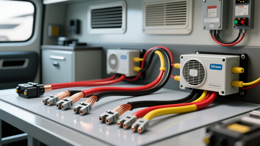
The RV & Van Conversion Mini-Split Power Challenge
When upgrading an expedition vehicle, Sprinter van, or Skoolie with a high-efficiency ductless HVAC system, selecting the correct conductor size is critical for both safety and performance. Unlike factory-installed 12V DC rooftop air conditioners, residential-style mini-splits (such as 9,000 to 12,000 BTU models from Pioneer, Senville, or MrCool) operate on 120V or 240V AC power. This necessitates a robust inverter setup and heavy-duty AC wiring from your inverter's output to the exterior condenser and interior evaporator units. For 120V AC systems drawing up to 15 amps continuously, utilizing 10 gauge wire for mini split installations has become the gold standard in the overlanding and RV conversion community.
The primary challenge in automotive and mobile environments is that residential electrical codes do not account for the severe vibration, thermal cycling, and chassis flex inherent to vehicles. A wire that is perfectly safe in a stationary home can quickly fail due to work-hardening and metal fatigue when mounted to a moving chassis. This guide details the exact specifications, routing techniques, and termination standards required to safely integrate 10 AWG wiring into your mobile mini-split upgrade project.
Why 10 Gauge Wire for Mini Split Systems is the Sweet Spot
A typical 120V, 9,000 BTU inverter-compressor mini-split has a Running Load Amps (RLA) rating of roughly 8 to 11 amps. Under the National Electrical Code (NEC) guidelines, continuous loads (those operating for three hours or more) must be calculated at 125% of their maximum draw. This pushes the baseline requirement to roughly 13.75 amps. While 14 AWG wire is technically rated for 15 amps, using it in a mobile environment is highly discouraged due to voltage drop and thermal derating.
By stepping up to 10 gauge wire for mini split applications, you gain several critical advantages:
- Voltage Drop Mitigation: In a van or RV, the inverter is often located deep inside a battery compartment, requiring a 20 to 40-foot cable run to the exterior mini-split condenser. 10 AWG copper keeps the voltage drop well under the recommended 3% threshold, ensuring the inverter-compressor receives clean, stable voltage.
- Surge Capacity: Even with soft-start inverter compressors, the initial startup surge can momentarily spike to 20+ amps. 10 AWG wire handles these transient thermal loads without degrading the insulation.
- Thermal Derating Buffer: Wires routed through engine bays, under floorboards, or inside insulated wall cavities experience high ambient temperatures, which reduces their ampacity. 10 AWG provides a necessary safety buffer.
10 AWG Stranded Copper Specifications Chart
| Specification | 10 AWG Fine-Stranded Copper (UL1015/UL1283) | 10 AWG Solid Core THHN (Residential) |
|---|---|---|
| Max Ampacity (Chassis/Single) | 30 Amps | 30 Amps |
| Max Ampacity (Bundled/Conduit) | 18-21 Amps (Derated) | 15 Amps (Derated) |
| Resistance per 1,000 ft | 1.018 Ohms | 0.998 Ohms |
| Vibration Resistance | Excellent (Flexible) | Poor (Prone to Snapping) |
| Automotive/Mobile Use | Highly Recommended | Strictly Prohibited |
Note: Always refer to the NFPA 70 / NEC Article 551 for specific recreational vehicle wiring mandates regarding conductor types and bundling derations.
Automotive vs. Residential: The Stranding Imperative
The most common mistake DIY van builders make is purchasing standard Romex or solid-core THHN wire from a local hardware store for their 120V AC mini-split runs. Solid-core wire is designed for stationary structures. When subjected to the low-frequency, high-amplitude vibrations of a diesel or gas engine and road chatter, solid copper undergoes 'work hardening.' Over time, the copper becomes brittle and will snap inside the insulation, leading to arcing, melted connectors, or catastrophic fire.
For any 10 gauge wire for mini split runs in a vehicle, you must use fine-stranded copper wire rated for at least 90°C to 105°C. Look for UL1015, UL1283, or SAE J1128 compliant hook-up wire. The stranding allows the conductor to flex and absorb chassis vibration without fatiguing the copper strands. Furthermore, the insulation on automotive-grade stranded wire is typically oil, grease, and moisture-resistant, which is vital when routing cables through a vehicle's undercarriage or wheel wells to reach an externally mounted condenser.
Breaker Selection: C-Curve vs. Standard Thermal
Wiring the circuit correctly is only half the battle; protecting it is the other. Mini-split compressors, even modern inverter-driven ones, generate harmonic distortion and momentary inrush currents. If you use a standard residential thermal-magnetic breaker or a standard automotive blade fuse on the AC output side, you may experience nuisance tripping every time the compressor ramps up to maximum frequency.
When sizing your 20A breaker for a 10 AWG 120V mini-split circuit, specify a C-Curve or D-Curve Miniature Circuit Breaker (MCB). C-Curve breakers are designed to trip between 5 and 10 times the rated current, accommodating the brief magnetic inrush of HVAC motors and transformers without opening the circuit during normal startup sequences. For the DC side (battery to inverter), consult the Victron Energy Wiring Unlimited Guide to properly size your Class-T or ANL fuses based on the inverter's continuous wattage rating.
Step-by-Step: Terminating 10 AWG in High-Vibration Environments
Proper termination is where most mobile electrical failures occur. The connection points at the inverter's AC output block and the mini-split's exterior disconnect box must be impervious to moisture and vibration.
- Strip the Insulation: Use a precision wire stripper calibrated for 10 AWG stranded wire. Avoid nicking the outer strands, as this creates weak points for corrosion and breakage.
- Select the Right Terminal: Use a closed-barrel, #10 stud ring terminal made of tinned copper. Do not use open-barrel or stamped brass terminals for high-current HVAC applications.
- Hex Crimping: Use a dedicated hex-crimp tool (such as those from TE Connectivity or Knipex) rather than a standard indent crimper. A hex crimp uniformly compresses the copper strands and the terminal barrel into a solid, gas-tight mass, eliminating pockets where moisture could cause galvanic corrosion.
- Adhesive-Lined Heat Shrink: Slide a piece of dual-wall, adhesive-lined heat shrink over the wire before crimping. After crimping, apply heat until the internal sealant melts and oozes slightly from the edges. This creates a waterproof seal that prevents capillary action from drawing moisture under the insulation.
- Torque to Spec: When attaching the ring terminal to the inverter's AC busbar or the mini-split disconnect, use a calibrated inch-pound torque wrench. Overtightening will deform the terminal and reduce surface contact area, leading to a high-resistance hot spot. Undertightening will allow vibration to loosen the connection.
Routing and Securing the AC Cable Harness
When routing your 10 gauge wire for mini split power from the interior inverter bay to the exterior condenser, you must protect the cable from physical damage. Use split-loom corrugated tubing or braided nylon sleeving to protect the wire bundle from sharp sheet metal edges and road debris. Secure the harness every 12 to 18 inches using UV-resistant, stainless-steel backed P-clamps or heavy-duty zip ties mounted to existing chassis brackets. Never route 120V AC cables parallel to low-voltage DC data cables (such as CAN bus or thermostat communication wires) to prevent electromagnetic interference (EMI), which can cause the mini-split's logic board to throw communication errors.
Troubleshooting Common Mini-Split Power Failures
Even with perfectly sized 10 AWG wire, mobile mini-split installations can experience unique issues. Use this diagnostic matrix to identify faults:
- Symptom: Inverter shuts down with 'Overload' or 'Low Voltage' alarm during mini-split startup.
Cause: Voltage drop on the DC side (battery to inverter) is too high, causing the inverter to pull excessive DC amps to compensate for the AC surge.
Fix: Upgrade the DC battery cables to 2/0 AWG or 4/0 AWG and ensure busbar connections are torqued. - Symptom: Mini-split displays 'Communication Error' (E1 or similar code).
Cause: EMI interference from poorly shielded AC wiring or loose neutral connections causing harmonic noise.
Fix: Verify the 10 AWG neutral (White) and ground (Green) are securely bonded at the correct terminal blocks and ensure AC wires are separated from the low-voltage signal wire. - Symptom: Breaker trips randomly after hours of normal operation.
Cause: Thermal derating due to wire bundling or high ambient temperatures in the inverter compartment.
Fix: Reroute wires away from heat sources (like exhaust components or inverter heat sinks) and ensure the breaker is rated for the ambient temperature of the enclosure.
Final Inspection and Commissioning
Before energizing the system, perform a continuity test from the inverter output to the mini-split disconnect to ensure no short circuits exist between Line, Neutral, and Ground. Once verified, power on the inverter and measure the AC voltage at the disconnect box using a True-RMS multimeter. You should read between 115V and 125V. Finally, engage the disconnect and monitor the 10 AWG wire and termination points with an infrared thermal camera after the mini-split has been running under load for 30 minutes. Any termination point showing a temperature delta of more than 10°F above the ambient wire temperature indicates a poor crimp or loose connection that must be re-terminated immediately. By adhering to these rigorous automotive-grade standards, your 10 gauge wire for mini split upgrade will provide reliable, safe climate control for years of off-grid exploration.