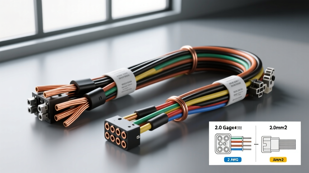
The '2.0 Gauge' Terminology Trap: AWG vs. Metric
When automotive enthusiasts and fabricators search for '2.0 gauge wire,' they are usually navigating a frustrating colloquialism that conflates two entirely different electrical standards. In the automotive aftermarket, this term generally refers to either 2 AWG (American Wire Gauge) heavy-duty battery cable or 2.0 mm² (metric cross-section) primary wire. Confusing the two can lead to catastrophic electrical failures: using 2.0 mm² wire for a high-amp alternator upgrade will result in an immediate meltdown, while using 2 AWG wire for an ECU sensor circuit is physically impossible to terminate into standard OEM connectors.
This comprehensive gauge reference breaks down the exact specifications, ampacity ratings, and modification applications for both 2 AWG and 2.0 mm² wire. Whether you are upgrading the charging system on a high-output LS-swapped vehicle or extending OEM harnesses for a standalone ECU, understanding the precise metallurgical and dimensional differences is critical for a safe, reliable build.
2 AWG Wire: The Heavy-Duty Upgrade Standard
In the context of high-current automotive modifications, '2.0 gauge' almost always means 2 AWG. This massive conductor is the baseline requirement for high-output alternator upgrades (typically 200A to 250A), massive car audio capacitor banks, and heavy-duty winch solenoid feeds. According to the SAE J1128 Low Tension Cable standard, automotive battery cable must meet strict thermal and flexibility requirements that differentiate it from standard building wire.
2 AWG Copper Specifications Chart
| Specification | SAE J1128 (Battery Cable) | Standard Building Wire (THHN) |
|---|---|---|
| Conductor Area | 66,360 Circular Mils (33.6 mm²) | 66,360 Circular Mils |
| Stranding (Flexibility) | 1332 strands of 30 AWG (Ultra-Flex) | 7 to 19 strands (Stiff) |
| Outer Diameter (OD) | 0.33 inches (8.38 mm) | 0.42 inches (with thick insulation) |
| Resistance @ 20°C | 0.1563 Ohms per 1,000 ft | 0.1563 Ohms per 1,000 ft |
| Max Ampacity (Chassis) | 175A - 200A (Engine Bay derated) | 115A (NEC 75°C column) |
| Insulation Material | EPDM or Cross-linked PE (105°C) | PVC / Nylon (75°C - 90°C) |
Note: Always use SAE J1128 or ISO 6722 compliant fine-strand wire for automotive applications. The engine bay environment requires high strand counts to withstand constant high-frequency vibration without suffering from work-hardening and copper fatigue.
Executing the 'Big Three' Upgrade with 2 AWG
The 'Big Three' wiring upgrade involves replacing or supplementing the factory alternator-to-battery positive, battery-to-chassis ground, and engine-to-chassis ground cables. As detailed by MAD Enterprises High-Output Charging guidelines, upgrading to 2 AWG is mandatory when installing alternators rated above 140 amps to prevent voltage drop and alternator diode failure.
- Alternator to Battery Positive: Route 2 AWG red wire from the alternator B+ terminal to the positive battery post. Use a high-amp ANL fuse (rated 20% higher than max alternator output) within 18 inches of the battery.
- Engine Block to Chassis Ground: Attach 2 AWG black wire from a clean, bare-metal point on the engine block (often utilizing an unused bellhousing bolt) to a dedicated chassis ground stud.
- Battery Negative to Chassis Ground: Run 2 AWG black wire from the battery negative terminal to a clean chassis point near the battery tray.
Torque Specifications: When terminating the alternator B+ terminal (typically an M8 brass nut), torque to exactly 8-10 Nm (6-7.5 lb-ft). Over-torquing will strip the soft brass threads on the alternator diode bridge, requiring a complete unit teardown to repair.
2.0 mm² Wire: Precision ECU and Accessory Routing
If your project involves European vehicles, modern OEM harness extensions, or standalone ECU wiring (like Haltech or MoTeC), '2.0 gauge' refers to 2.0 mm² metric wire. This is roughly equivalent to 14 AWG (which has a cross-section of 2.08 mm²). This wire is the backbone for high-draw accessories, relay trigger feeds, electric cooling fan relays, and heavy-duty sensor grounds.
2.0 mm² Metric Automotive Specifications
| Specification | ISO 6722-1 Class B (Thin Wall) | DIN 72551 (Standard Wall) |
|---|---|---|
| Nominal Area | 2.0 mm² | 2.0 mm² |
| AWG Equivalent | ~14 AWG | ~14 AWG |
| Stranding | 64 strands x 0.20 mm | 64 strands x 0.20 mm |
| Max Outer Diameter | 2.7 mm | 3.4 mm |
| Resistance @ 20°C | 9.42 mOhm/m (max) | 9.42 mOhm/m (max) |
| Continuous Current | 25A (Single core in free air) | 22A (Bundled in harness) |
| Temperature Rating | 105°C | 105°C |
For detailed OEM compliance standards regarding metric automotive cabling, refer to the ISO 6722-1 Road Vehicles Single-Core Wire standard. Thin-wall (Class B) insulation is preferred in modern engine bays as it reduces harness bulk and weight while maintaining high thermal resistance.
Terminating 2.0 mm² for Deutsch DT Connectors
2.0 mm² wire is the absolute maximum size that can be pinned into standard Deutsch DT series connectors (commonly used for off-road lighting, winch controls, and aftermarket sensors). The DT solid contacts (Part Number 1060-14-0122) are designed for 14-18 AWG wire. Attempting to force 12 AWG (3.0 mm²) into a DT contact will damage the crimp barrel and compromise the internal wire seal.
- Wire Strip Length: Strip exactly 6mm (0.24 inches) of insulation. Do not nick the copper strands.
- Crimping Tool: Use a dedicated Deutsch DT crimp tool (or equivalent open-barrel crimper with a 14 AWG cavity). The crimp should feature a distinct 'B' or 'heart' shape when viewed from the end, ensuring the wire insulation is captured by the rear grip wings and the copper is compressed by the front conductor wings.
- Seal Insertion: Slide the silicone wedge seal onto the wire before crimping. After crimping, insert the pin into the housing until you feel and hear a distinct mechanical 'click', then insert the secondary wedge lock to prevent terminal back-out.
Crimping, Torque, and Termination Protocols
The failure point in 90% of automotive wiring upgrades is not the wire itself, but the termination. Improper crimping leads to increased resistance, localized heat generation, and eventual voltage drop.
Terminating 2 AWG Heavy Cable
Never use standard pliers or hammer crimpers for 2 AWG battery cable. The high strand count requires massive, even compression to eliminate air pockets within the copper bundle.
- Use a 16-ton hydraulic hex crimper or a heavy-duty ratcheting hex crimper.
- Select the 2 AWG hex die (often color-coded red or brown depending on the manufacturer).
- Slide 3:1 ratio adhesive-lined dual-wall heat shrink onto the wire before crimping. Standard PVC heat shrink will not seal against moisture ingress, leading to green copper oxide (galvanic corrosion) inside the terminal.
- Crimp the terminal, ensuring the hex indentation is centered on the barrel. Apply heat to the shrink tubing until the inner adhesive layer melts and oozes slightly from the edges, creating a watertight environmental seal.
Diagnostic Troubleshooting: Voltage Drop Testing
After completing a 2 AWG Big Three upgrade or a 2.0 mm² accessory harness build, you must validate the integrity of the circuit using a digital multimeter (DMM). A resistance test (ohms) is insufficient for high-current automotive circuits; you must perform a dynamic Voltage Drop Test under load.
Step-by-Step Voltage Drop Procedure
- Set your DMM to DC Volts (20V scale).
- Start the vehicle and turn on maximum electrical load (headlights, A/C blower, rear defroster, and audio system).
- Place the red probe directly on the alternator B+ terminal (the metal post, not the wire).
- Place the black probe directly on the battery positive post (the lead post, not the clamp).
- Read the display. A healthy 2 AWG charging circuit will show a voltage drop of 0.10V or less.
- Repeat the process for the ground side: Red probe on the battery negative post, black probe on the alternator casing (bare metal). The drop should also be 0.10V or less.
Common Failure Modes: If your voltage drop exceeds 0.25V, you have a high-resistance fault. This is almost always caused by an under-crimped 2 AWG terminal, a missing star washer on a chassis ground (paint or powder coating acting as an insulator), or an M8 terminal nut that has vibrated loose due to missing threadlocker. Always apply a thin layer of NO-OX-ID A-Special or Noalox conductive grease to bare-metal ground points to prevent aluminum-to-copper galvanic corrosion over time.
Summary
Whether you are pulling 2 AWG ultra-flex cable through a firewall for a 250-amp alternator or carefully pinning 2.0 mm² thin-wall wire into a waterproof Deutsch connector for a fuel pressure sensor, respecting the specific dimensional and metallurgical standards of your wire is non-negotiable. By adhering to SAE and ISO specifications, utilizing proper hydraulic and open-barrel crimping techniques, and validating your work with dynamic voltage drop testing, your electrical modifications will survive the harsh thermal and vibrational realities of the automotive environment.