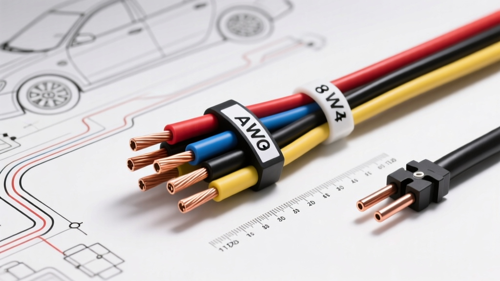
The Inverse Logic of American Wire Gauge (AWG)
When building custom harnesses, upgrading charging systems, or diagnosing voltage drop, one of the most common questions from enthusiasts and technicians is: which gauge wire is thicker? The American Wire Gauge (AWG) system operates on an inverse logarithmic scale, meaning that a smaller numerical gauge indicates a thicker wire with a larger cross-sectional area. For example, 4 AWG wire is significantly thicker than 8 AWG wire, and 0 AWG (often written as 1/0) is thicker still.
This counterintuitive sizing originates from the historical wire manufacturing process. According to the ASTM B258 standard, the AWG number historically represented the number of drawing dies a metal rod had to be pulled through to reach its final diameter. A raw rod might start at gauge 0, and each successive pull through a smaller die increased the gauge number while decreasing the wire's physical thickness. Today, while wire is manufactured using advanced extrusion and stranding techniques, this inverse naming convention remains the global standard for North American automotive and electrical systems.
The Physics of Thickness: Cross-Sectional Area and Circular Mils
Understanding which gauge wire is thicker requires looking beyond the outer insulation jacket and focusing on the conductive copper stranding. The true measure of a wire's current-carrying capability is its cross-sectional area, typically measured in circular mils (cmil) or square millimeters (mm²).
- 4 AWG Wire: Features a cross-sectional area of approximately 41,740 circular mils (21.15 mm²). It typically consists of hundreds of fine 30 AWG copper strands to maintain flexibility in tight engine bays.
- 8 AWG Wire: Features a cross-sectional area of roughly 16,510 circular mils (8.37 mm²). While robust, it possesses less than half the conductive mass of 4 AWG.
Because electrical resistance is inversely proportional to cross-sectional area, the thicker 4 AWG wire exhibits drastically lower resistance per foot. In high-current automotive environments, this thickness is the primary defense against resistive heating and catastrophic voltage drop.
SAE J1128 vs. NEC: Automotive vs. Building Wire Ampacity
A critical mistake made by novice fabricators is referencing the National Electrical Code (NEC) ampacity charts for automotive wiring. The NFPA 70 (NEC) standards are designed for stationary building wire in ambient temperatures of 30°C (86°F). Automotive engine bays routinely exceed 100°C (212°F), and wires are often bundled tightly together, restricting heat dissipation.
Therefore, automotive wire must be sized according to SAE International J1128 standards, which apply strict thermal derating factors to the wire's ampacity based on insulation type (e.g., PVC, XLPE, or Teflon) and ambient temperature.
Technical Specification Chart: AWG Thickness & SAE Automotive Ampacity
| AWG Size | Nominal Diameter (in) | Nominal Diameter (mm) | Circular Mils | Ohms per 1,000 ft (at 20°C) | SAE J1128 Max Ampacity (Single Wire in Free Air) |
|---|---|---|---|---|---|
| 2 AWG | 0.2576 | 6.54 | 66,360 | 0.1563 | 210A |
| 4 AWG | 0.2043 | 5.19 | 41,740 | 0.2485 | 160A |
| 8 AWG | 0.1285 | 3.26 | 16,510 | 0.6282 | 90A |
| 10 AWG | 0.1019 | 2.59 | 10,380 | 0.9989 | 70A |
| 12 AWG | 0.0808 | 2.05 | 6,530 | 1.5880 | 50A |
Note: Ampacity ratings drop significantly when wires are bundled in corrugated loom or routed through high-heat firewall grommets. Always apply a 20-30% derating factor for under-hood harness bundles.
Automotive Deep Dive: 4 AWG vs 8 AWG in High-Current Circuits
To practically answer which gauge wire is thicker and why it matters, let us examine two common high-current automotive applications: LS V8 starter upgrades and high-output alternator charging systems.
Case Study 1: LS-Swap Starter Cables
When performing an LS V8 swap into a classic chassis, the starter motor can draw upwards of 200 to 250 amps during initial cranking, especially if the engine is cold or has high compression. Using 8 AWG wire for a 15-foot run from the trunk-mounted battery to the starter solenoid will result in severe voltage drop. The thinner 8 AWG wire acts as a resistor, choking the current and causing the starter to spin sluggishly.
The Fix: Use 4 AWG (or thicker 2 AWG) fine-strand welding cable. The thicker copper mass ensures the starter receives a full 12.2V+ during cranking. For the termination at the starter, use a heavy-duty copper ring terminal (M10 stud size) and torque the solenoid B+ nut to exactly 11 Nm (8 lb-ft) to prevent arcing. Protect the 4 AWG cable with high-temp fiberglass sleeving where it passes near the exhaust headers.
Case Study 2: High-Output Alternator Upgrades
Upgrading from a stock 80A alternator to a 140A aftermarket unit (such as a Powermaster or MechMan) requires re-evaluating the main charge wire. Many enthusiasts mistakenly reuse the factory 8 AWG or 10 AWG wire. While 8 AWG is rated for roughly 90A in free air, pushing 140A through it will cause the wire to overheat, melting the PVC insulation and potentially causing an under-hood fire.
The Fix: Run a dedicated 4 AWG red primary wire from the alternator B+ post directly to the battery positive terminal. Install a 150A Mega Fuse (or ANL fuse) within 7 inches of the battery terminal. Crucially, you must also upgrade the alternator sense wire. If the ECU or alternator voltage regulator senses voltage at the battery, but the undersized main wire is dropping 1.5 volts, the alternator will overcompensate, pushing 15.5V+ into the system and boiling the battery.
Failure Modes of Undersized (Too Thin) Wire
Choosing a wire that is too thin (a higher AWG number) for a high-current load introduces several cascading failure modes in modern vehicles:
- ECU Brownouts and Resets: Modern CAN bus networks and Engine Control Modules require a stable 13.5V to 14.5V supply. If a thin 12 AWG ground wire is used for a high-draw cooling fan relay, the voltage drop across the thin ground can raise the ECU's ground reference. This 'floating ground' confuses the 5V logic sensors, throwing phantom O2 sensor or MAF codes.
- Insulation Thermal Degradation: Standard automotive GXL or TXL wire features cross-linked polyethylene (XLPE) insulation rated for 125°C to 150°C. When a wire is undersized, I²R (current squared times resistance) heating will exceed this threshold. The insulation will become brittle, crack, and eventually short against the steel chassis.
- Connector Pin Melting: The heat generated in a thin wire travels down the copper strands directly into the connector cavity. It is common to see the plastic housing of a standard Delphi Packard 56-series connector melt and deform when fed by an undersized wire carrying continuous high amperage.
Termination, Crimping, and Hardware Specs for Thick Gauge Wire
Knowing which gauge wire is thicker is only half the battle; properly terminating thick wires like 4 AWG requires specialized tooling. Standard handheld ratcheting crimpers are entirely insufficient for 4 AWG and larger.
- Crimping Tooling: Use a hydraulic crimping tool with hexagonal or indenter dies specifically matched to the AWG size. A proper crimp on 4 AWG wire should yield a 'cold weld' where the copper strands fuse together, achieving a pull-out strength exceeding 300 lbs.
- Heat Shrink Selection: Always use dual-wall, adhesive-lined marine-grade heat shrink. When heated, the inner layer of thermoplastic adhesive melts and flows into the wire strands, creating a waterproof seal that prevents capillary action from drawing moisture under the insulation.
- Hardware Torque Specifications: When securing thick gauge ring terminals to battery posts, busbars, or grounding studs, proper clamping force is vital. For an M8 (8mm) grounding stud on a cylinder head or chassis rail, apply anti-oxidant compound (e.g., Noalox) and torque to 20 Nm (15 lb-ft). For M10 battery terminal lugs, torque to 15 Nm (11 lb-ft). Overtightening can strip soft aluminum threads or snap copper terminal studs.
Summary: Selecting the Correct Thickness
When asking which gauge wire is thicker, remember that physical thickness dictates electrical capacity. For low-current signals, sensor circuits, and CAN bus lines (typically drawing less than 2 amps), thinner wires like 18 AWG or 20 AWG are perfectly adequate and necessary for pin insertion into tight Deutsch or Molex connectors. However, for main power distribution, starter circuits, and high-output charging systems, relying on the robust cross-sectional area of 4 AWG or 2 AWG wire is non-negotiable for safety, reliability, and optimal vehicle performance.