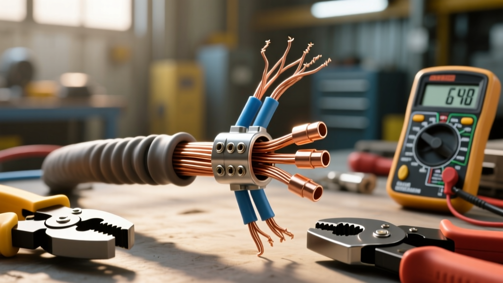
The Hidden Dangers of a Bad 6 Gauge Wire Splice
When working with high-current automotive circuits, the integrity of your connections is the difference between a reliable electrical system and a catastrophic vehicle fire. 6 AWG (American Wire Gauge) copper wire is a heavy-duty conductor typically utilized for alternator main feeds, winch relay circuits, EV battery management systems, and high-output audio amplifiers. In a standard 12-volt automotive environment, a 6 gauge wire is expected to carry anywhere from 50 to 75 amps continuously, and can handle brief surges exceeding 100 amps.
Because of the massive thermal energy generated by high-amperage circuits, a 6 gauge wire splice cannot be treated like a simple 18-gauge taillight extension. Any increase in electrical resistance at the splice point will result in localized heating, voltage drop, and eventual insulation meltdown. Unfortunately, many DIY mechanics and inexperienced installers apply low-amperage splicing techniques to heavy-gauge wiring. This guide outlines the most critical safety warnings and common mistakes made when splicing 6 AWG wire, ensuring your high-current circuits remain safe, efficient, and compliant with automotive engineering standards.
Mistake #1: Relying on Solder for High-Vibration, High-Amp Splices
One of the most pervasive myths in automotive wiring is that soldering is the ultimate, bulletproof method for joining wires. While solder is excellent for PCB boards and low-current, low-vibration sensor wires, it is highly dangerous for a 6 gauge wire splice in an engine bay or chassis environment.
The Physics of Solder Failure
Solder is a lead or tin-based alloy that has a significantly lower melting point than copper (typically around 360°F to 412°F for standard rosin-core solder, compared to copper's 1,984°F). If a high-amp circuit experiences a resistance spike, the joint will heat up. A properly crimped copper joint will dissipate this heat, but a soldered joint will literally melt, causing the splice to pull apart under the tension of the thick 6 AWG cable.
Furthermore, solder wicks into the copper strands via capillary action. This creates a rigid, inflexible section of wire right at the edge of the splice. In a vehicle, engine harmonics and chassis flex introduce constant vibration. The transition point between the flexible bare wire and the rigid soldered section becomes a stress concentrator, leading to copper fatigue, strand snapping, and ultimately an open circuit or an arc flash.
Mistake #2: Using the Wrong Crimping Tool (Jaw Misalignment)
To achieve a safe 6 gauge wire splice, you must create a 'gas-tight' cold weld between the copper strands and the terminal barrel. This requires immense mechanical force. A common and dangerous mistake is attempting to crush a 6 AWG butt splice using standard slip-joint pliers, lineman's pliers, or a cheap, non-ratcheting hand crimper.
The Requirement for Hexagonal Crimping
For 6 AWG wire, indent-style crimpers (which leave a single divot in the barrel) do not provide enough surface area compression to prevent the wire from pulling out under load. You must use a heavy-duty ratcheting crimper with a hexagonal die or a hydraulic crimper. A hex crimp compresses the barrel uniformly from all six sides, forcing the copper strands to deform and interlock with the terminal metal. According to SAE J1128 standards for low-tension primary cables, the mechanical pull-out force for a properly crimped 6 AWG terminal must exceed 300 pounds. Pliers simply cannot achieve this uniform deformation, leaving voids inside the barrel where moisture can enter and cause galvanic corrosion.
Mistake #3: Inadequate Insulation and Environmental Sealing
Wrapping a 6 gauge wire splice in standard vinyl electrical tape is a severe safety hazard. Under-hood temperatures in modern vehicles can easily exceed 125°C (257°F) near the exhaust manifolds or turbochargers. At these temperatures, the adhesive on vinyl tape turns to liquid, the tape unrolls, and the bare, high-current splice is left exposed to the elements and nearby metal chassis grounds.
The Dual-Wall Heat Shrink Mandate
The only acceptable insulation method for a heavy-gauge splice is dual-wall, adhesive-lined polyolefin heat shrink tubing.
- Outer Wall: Cross-linked polyolefin that resists abrasion, chemicals, and high heat (rated up to 125°C continuous).
- Inner Wall: A thermoplastic hot-melt adhesive that liquefies when heated, flowing into the crevices between the wire strands and the splice barrel, then hardening to form a waterproof, environmental seal.
Mistake #4: Twisting Thick Strands Before Crimping
Many installers instinctively twist the exposed copper strands of a wire before inserting it into a butt splice to 'keep them neat.' On 18-gauge wire, this is harmless. On 6 AWG wire, it is a critical error.
Twisting the heavy copper strands reduces the overall diameter of the wire bundle. When inserted into the splice barrel, the wire will fit loosely. When the hex crimp is applied, the terminal barrel will collapse unevenly, potentially cutting or shearing the outer copper strands. The correct technique is to strip the wire cleanly, leave the strands exactly as they were extruded, and gently push them straight into the barrel until they hit the internal stop.
Correct 6 AWG Splice Specification Chart
Use the following reference table to ensure your materials and tooling meet the rigorous demands of high-amperage automotive circuits.
| Parameter | Specification / Requirement |
|---|---|
| Wire Type | SAE J1128 SXL or GXL (Cross-linked polyethylene) |
| Strip Length | 5/8 inch (15.8 mm) - Do not nick strands |
| Splice Terminal | Non-insulated or adhesive-lined copper butt splice (Tin-plated) |
| Crimp Tooling | Heavy-duty ratcheting hex crimper or Hydraulic press |
| Die Size | Hex die sized specifically for 6 AWG (Usually marked #6 or Blue/Yellow depending on brand) |
| Insulation | 3/8' or 1/2' Dual-Wall Adhesive Heat Shrink (3:1 ratio) |
| Max Continuous Ampacity | 75 Amps (Single wire in free air, 90°C rating) |
Real-World Failure Case Study: High-Output Alternator Feed
Consider a common scenario: upgrading the alternator on a 2003 Chevrolet Silverado 2500HD (GMT800 platform) from the stock 105-amp unit to a 220-amp aftermarket unit to support a winch and auxiliary lighting. The factory 8 AWG charge wire is insufficient, so the installer upgrades to a 6 AWG SXL wire. However, the new wire is slightly too short to reach the battery positive terminal, requiring a 6 gauge wire splice to add an extra 12 inches of length.
The Mistake: The installer uses an indent-style hand crimper and wraps the joint in three layers of vinyl tape. The Result: Under heavy winching loads, the alternator pushes 180 amps through the circuit. The poorly crimped indent splice develops micro-ohms of resistance. Over three months, the localized heat degrades the vinyl tape, and galvanic corrosion forms inside the loose crimp barrel. The voltage drop at the splice reaches 1.5 volts. The Powertrain Control Module (PCM) detects the low voltage at the battery sense wire and throws a DTC P0562 (System Voltage Low), causing the transmission to enter limp mode and the ABS module to disable itself. The Fix: Cut out the corroded section, use a proper hex-crimped, adhesive-sealed butt splice, and route the wire away from the exhaust manifold to prevent ambient thermal degradation.
Step-by-Step Safe Splicing Protocol
- Disconnect Power: Always remove the negative battery terminal before cutting into any high-amperage feed wire to prevent dead shorts and arc flashes.
- Precision Stripping: Use a heavy-duty wire stripper designed for 6 AWG. Score the SXL insulation and pull it off. Never use a utility knife, as slicing into the copper strands compromises the wire's cross-sectional area and creates a hot spot.
- Prep the Heat Shrink: Slide the dual-wall heat shrink onto the wire before crimping. (A surprisingly common and frustrating mistake is crimping the splice and realizing the heat shrink is still on the table).
- Insert and Verify: Push the stripped wire into the butt splice until it bottoms out. Ensure no bare copper is visible outside the barrel on either side.
- Hex Crimp: Place the terminal into the correct 6 AWG hex die. Squeeze the ratcheting crimper until the tool releases. The crimp should be symmetrical and severely deformed.
- Pull Test: Give the wires a firm, sharp tug by hand. A proper cold-weld will not separate.
- Seal and Shrink: Center the heat shrink over the splice. Apply heat evenly with a heat gun until the tubing is tight and a small bead of adhesive oozes from both ends.
Authoritative References
For further reading on automotive electrical standards and heavy-gauge termination protocols, consult the following resources:
- SAE International - J1128: Low Tension Primary Cable (Details insulation types, temperature ratings, and wire gauge specifications).
- Delphi Automotive Connection Systems Manual (Provides in-depth engineering data on gas-tight crimping mechanics and pull-out force requirements).
- Madsen Wire & Cable Technical Guides (Offers practical application notes on hex crimping vs. indent crimping for heavy-gauge battery cables).