Why Connecting Four 12 AWG Wires is a Unique Challenge
In automotive electrical systems, 12 AWG (American Wire Gauge) is the undisputed workhorse for medium-to-high current circuits. You will frequently find 12 gauge wire powering fuel pumps, electric cooling fans, power window motors, and aftermarket lighting arrays. However, when a project requires you to figure out how to connect 4 12 gauge wires together into a single junction, beginners often hit a wall.
Unlike thin 18 AWG sensor wires, 12 AWG wire is thick, stiff, and carries enough amperage to cause a vehicle fire if a connection fails. Twisting four 12 AWG wires together by hand is physically exhausting and rarely results in a secure mechanical bond. Furthermore, attempting to stuff four thick copper bundles into a standard butt connector will result in a loose crimp, massive voltage drop, and eventually, melted insulation. This guide breaks down the three safest, most reliable methods to join four 12 AWG wires, tailored specifically for automotive environments where vibration and heat are constant threats.
12 AWG Automotive Wire Specifications & Ampacity
Before making any connections, it is crucial to understand the physical and electrical properties of the wire you are working with. Most modern automotive wiring uses cross-linked polyethylene insulation (GXL, TXL, or HDT) which is thinner and more heat-resistant than standard PVC wire, allowing for tighter routing in engine bays.
| Specification | 12 AWG Automotive Wire (GXL/TXL) |
|---|---|
| Cross-Sectional Area | 3.00 mm² (Approx. 6,530 Circular Mils) |
| Standard Stranding | 19 x 0.40mm (or 41 strands in high-flex applications) |
| Maximum Ampacity (Chassis Wiring) | 20 Amps (Continuous) |
| Maximum Ampacity (Short Engine Bay Runs) | Up to 25 Amps (TXL 125°C rated) |
| Resistance per 1,000 ft | 1.588 Ohms (at 20°C) |
| Common Automotive Uses | Fuel pumps, 20A fused accessory circuits, horn relays |
Reference: For comprehensive ampacity and voltage drop calculations across varying lengths, consult the Del City Wire Gauge & Ampacity Charts.
Method 1: Power Distribution Blocks (The Safest Route)
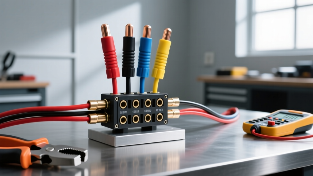
If your goal in connecting four 12 gauge wires is to distribute power from a main battery feed to multiple accessories (or to consolidate four separate ground wires to a single chassis point), a power distribution block is the absolute best method. It requires no crimping, no soldering, and allows for easy troubleshooting later.
Step-by-Step Distribution Block Wiring
- Select the Right Block: Choose a brass or copper distribution block with set-screws. Avoid aluminum blocks for high-current automotive use unless they are specifically plated to prevent galvanic corrosion with copper wire.
- Strip the Wires: Strip exactly 3/8-inch of insulation from the ends of all four 12 AWG wires. Do not leave exposed copper outside the block, as this invites corrosion and short circuits.
- Apply Anti-Oxidant Paste: If using an aluminum block, apply a tiny drop of Noalox or similar anti-oxidant compound to the stripped copper strands. This prevents the formation of aluminum oxide, which acts as an insulator and causes heat buildup.
- Insert and Torque: Insert the wires into the block ports. Tighten the set-screws using a properly sized hex key or flathead screwdriver. Apply firm pressure until the wire cannot be pulled out by hand.
- Seal the Block: For under-hood applications, cover the exposed entry points of the distribution block with liquid electrical tape or a silicone-based dielectric grease to block moisture ingress.
Method 2: Parallel Crimping with Closed-End Connectors
Sometimes, you need to splice four wires together in a harness where a bulky distribution block will not fit. A common scenario is adding a relay trigger wire into an existing ignition circuit. For example, if you are tapping into a GM ignition switch harness, you might need to join the factory pink (12V switched) wire with three new 12 AWG feeds for aftermarket accessories.
Closed-end connectors (often called 'pigtails' or 'wire nuts' in household wiring, but specifically designed for automotive crimping) are ideal here. You will need a 12-10 AWG stepped closed-end connector (such as the CE2-12 copper crimp sleeve).
The Ratcheting Crimp Technique
- Stagger the Stripping: Strip the four 12 AWG wires so they are all exactly the same length (usually 5/16-inch for closed-end connectors).
- Align and Twist: Hold the four stripped ends perfectly parallel. Do not pre-twist them heavily, as this makes insertion into the crimp barrel difficult and can splay the strands.
- Insert into the Barrel: Push the parallel wires deep into the copper barrel of the closed-end connector. You should feel them bottom out.
- Use a Ratcheting Crimper: Never use standard slip-joint pliers for 12 AWG crimps. Use a dedicated ratcheting wire crimper designed for non-insulated or vinyl-insulated terminals. The ratcheting mechanism ensures the exact amount of pressure is applied to cold-weld the copper strands together.
- The Pull Test: Give each of the four wires a firm tug. If any wire pulls out, the crimp failed and must be cut off and redone.
Method 3: The Western Union Splice & Solder Technique
For permanent, waterproof harness repairs where the junction will be wrapped in Tesa tape and buried deep inside a dashboard or frame rail, soldering is the traditionalist's choice. However, soldering four 12 AWG wires requires serious heat. A standard 30-watt electronics soldering iron will result in a 'cold joint' because the thick copper acts as a massive heat sink, drawing heat away from the solder.
Expert Soldering Steps for Heavy Gauge Wire
- Prep the Heat Shrink: Slide a piece of 3:1 ratio, adhesive-lined marine heat shrink over the main harness before you start splicing. The adhesive lining melts and creates a waterproof seal, which is critical for preventing green corrosion (copper oxide) inside the strands.
- Tin the Wires Individually: Using a 100W+ soldering gun or iron, apply 60/40 rosin-core solder to each of the four stripped 12 AWG wires individually. This process, called 'tinning', binds the strands together and makes the final splice much easier.
- The Modified Western Union Splice: Because four 12 AWG wires are too thick for a standard woven Western Union splice, twist two wires together in a tight X-splice, and twist the other two together in a separate X-splice. Then, hook the two pairs together and wrap them tightly.
- Sweat the Joint: Apply the tip of your high-wattage iron to the joint and feed solder until it wicks completely into the center of the splice. The solder should flow smoothly and look shiny. If it looks dull and clumpy, you have a cold joint.
- Seal and Shrink: Once the joint cools, slide the adhesive heat shrink over the splice. Apply heat evenly with a heat gun until the adhesive oozes out of both ends. For detailed harness wrapping and soldering standards, refer to the Painless Performance Wiring Guides.
Real-World Automotive Applications & Color Codes
When connecting four wires, you are usually building a junction node. Here are common scenarios where this is required:
- Aftermarket Fuel Pump Hot-Wire: Connecting the factory fuel pump relay feed (often grey or dark green), the new 12 AWG power feed from the battery, the trigger wire to the relay, and a diagnostic pigtail.
- Off-Road Lighting Bus: Joining four 12 AWG ground wires from a set of LED rock lights or pod lights to a single 12 AWG ground strap bolted to the chassis.
- Car Audio Power Distribution: While main amplifier feeds usually require 4 AWG or 8 AWG, distributing power to line-out converters, DSPs, and secondary relays often requires ganging multiple 12 AWG feeds together at the distribution block.
Troubleshooting Voltage Drop and Heat Buildup
According to the SAE J1128 Standard for Low Tension Cable, automotive wiring must withstand extreme thermal and mechanical stress. If your 4-way 12 AWG junction is failing, look for these symptoms:
- Symptom: Accessories dim or operate slowly when multiple circuits are active.
Cause: Voltage drop across a loose crimp or cold solder joint. The resistance at the junction generates heat and drops the voltage reaching the component.
Fix: Use a digital multimeter to measure voltage across the junction under load. Any reading over 0.1V indicates a failing connection that must be cut and redone. - Symptom: Melted or discolored insulation near the junction.
Cause: The junction is acting as a resistor due to splayed copper strands outside the crimp barrel, or the soldering iron burned the insulation during assembly, compromising the SAE thermal ratings.
Fix: Cut back the wire to clean, undamaged copper and redo the connection, ensuring the heat source is kept strictly on the metal, not the insulation.
Mastering how to connect 4 12 gauge wires safely is a fundamental skill that separates amateur wiring jobs from professional, reliable automotive electrical builds. Always prioritize mechanical strength before electrical conductivity, and never compromise on the quality of your crimping tools or heat shrink materials.